
Spec Sheet


POWERCOMMAND
®
OTEC TRANSFER SWITCH SPEC SHEET
ENCLOSURE
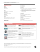
The transfer switch and control are wall-mounted in a key-locking enclosure. Wire bend space complies with 2017 NEC.
DIMENSIONS – TRANSFER SWITCH IN UL TYPE 1 ENCLOSURE
Frame Amperage rating (A) Height Width Depth Weight
in mm in mm in mm lb kg
A 125 27 686 20.5 521 12 305 82 37
B 225 35.5 902 26 660 16 406 165 75
C 400, 600 54 1372 25.5 648 18 457 225 102
DIMENSIONS – TRANSFER SWITCH IN UL TYPE 3R ENCLOSURE
Frame Amperage rating (A) Height Width Depth Weight Cabinet Type
in mm in mm in mm lb kg
A 125 34 864 26.5 673 12.5 318 125 57 3R
B 225 42.5 1080 30.5 775 16 406 1118 97 3R
C 400, 600 59 1499 27.5 699 16.5 419 275 125 3R
OTEC DRAWING PART NUMBERS
Outline Drawing
Frame
Amperage
rating (A)
Type 1 Type 3R
A 125 0310-0544 0310-0453
B 225 0310-0414 0310-0454
C 400, 600 0310-1307 0310-1315
WIRING DIAGRAM PART NUMBERS
Wiring Diagram
Frame
Amperage
rating (A)
Utility to Genset
(480 V)
Interconnection
A 125
A065K034 A065H780B 225
C 400, 600
ENCLOSURE ACCESS FOR CABLE INSTALLATION AND MAINTENANCE
All frames allow for top, side, and bottom cable entry. NEC Requires Minimum 36” Front Access. Additional
front clearance is needed to remove the mechanism. Refer to the outline drawing.
TRANSFER SWITCH LUG CAPACITIES
Frame Amperage rating (A) Cables per phase Size
A 125 1 #12 AWG-2/0
B 225 1 #6 AWG – 300MCM
C
400 2 One #4 AWG – 250 MCM
600 2 250 – 500 MCM
*All lugs 90°C rated and accept copper or aluminum wire unless indicated otherwise.
Refer to the latest NFPA 70 Article 310 - Conductors for general wiring for the ampacity calculations.