
Install Manual
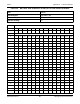
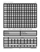

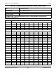
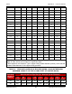
Table Of Contents
- Table of Contents
- 1. Important Safety Instructions
- 1.1 Save These Instructions
- 1.2 General Information
- 1.3 General Precautions
- 1.4 Generator Set Voltage Is Deadly
- 1.5 Engine Exhaust Is Deadly
- 1.6 Fuel and Fumes Are Flammable
- 1.7 Batteries Can Explode
- 1.8 Starting Batteries
- 1.9 Moving Parts Can Cause Severe Personal Injury or Death
- 1.10 The Hazards of Carbon Monoxide
- 2. Introduction
- 3. Pre-Installation Considerations
- 4. Installation
- 5. Startup and Configuration
- 5.1 "Establishing Communications" Message
- 5.2 "Clock Setup" Screen
- 5.3 "Exercise" Screen
- 5.4 "Brightness and Contrast" Screen
- 5.5 "About" Screen
- 5.6 "Event Log" Screen
- 5.7 "Fault Log" Screen
- 5.8 "System Status" Screen
- 5.9 "Mode" Screen
- 5.10 Automatic Load Management
- 5.11 Manual Start Sequence (Local)
- 5.12 Checklist
- 5.13 Startup
- 6. Remote Monitoring System (RMS) Description
- Appendix A. Fuel Line Selection
- Appendix B. Outline and System Drawings
- Appendix C. Wiring Diagrams

Appendix A. Fuel Line Selection 8-2019
88 A062J678 (Issue 2)Copyright © 2019 Cummins Inc.
650 18 38 71 145 218 420 669 1180 2410 4360 7070 14500 26400 41800
700 17 36 68 140 209 403 643 1140 2320 4190 6790 14000 25300 40100
750 17 35 66 135 202 389 619 1090 2230 4040 6540 13400 24400 38600
800 16 34 63 130 195 375 598 1060 2160 3900 6320 13000 23600 37300
850 16 33 61 126 189 363 579 1020 2090 3780 6110 12600 22800 36100
900 15 32 59 122 183 352 561 992 2020 3660 5930 12200 22100 35000
950 15 31 58 118 178 342 545 963 1960 3550 5760 11800 21500 34000
1000 14 30 56 115 173 333 530 937 1910 3460 5600 11500 20900 33100
1100 14 28 53 109 164 316 503 890 1810 3280 5320 10900 19800 31400
1200 13 27 51 104 156 301 480 849 1730 3130 5070 10400 18900 30000
1300 12 26 49 100 150 289 460 813 1660 3000 4860 9980 18100 28700
1400 12 25 47 96 144 277 442 781 1590 2880 4670 9590 17400 27600
1500 11 24 45 93 139 267 426 752 1530 2780 4500 9240 16800 26600
1600 11 23 44 89 134 258 411 727 1480 2680 4340 8920 16200 25600
1700 11 22 42 86 130 250 398 703 1430 2590 4200 8630 15700 24800
1800 10 22 41 84 126 242 386 682 1390 2520 4070 8370 15200 24100
1900 10 21 40 81 122 235 375 662 1350 2440 3960 8130 14800 23400
2000 NA 20 39 79 119 229 364 644 1310 2380 3850 7910 14400 22700
TABLE 23. NATURAL GAS SEMIRIGID COPPER TUBING SIZING
Gas: Natural
Inlet Pressure: Less than 2 psi
Pressure Drop: 0.5 in. water column
Specific Gravity: 0.6
Tube Size (in.)
Nominal K & L: 1⁄4 3⁄8 1⁄2 5⁄8 3⁄4 1 11⁄4 11⁄2 2
Nominal ACR: 3⁄8 1⁄2 5⁄8 3⁄4 7⁄8 11⁄8 13⁄8 — —
Outside: 0.375 0.5 0.625 0.75 0.875 1.125 1.375 1.625 2.125
Inside:* 0.305 0.402 0.527 0.652 0.745 0.995 1.245 1.481 1.959
Length (ft.) Capacity in Cubic Feet of Gas per Hour
10 27 55 111 195 276 590 1,060 1,680 3,490