
Install Manual
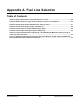
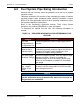
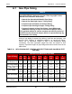
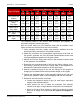
Table Of Contents
- Table of Contents
- 1. Important Safety Instructions
- 1.1 Save These Instructions
- 1.2 General Information
- 1.3 General Precautions
- 1.4 Generator Set Voltage Is Deadly
- 1.5 Engine Exhaust Is Deadly
- 1.6 Fuel and Fumes Are Flammable
- 1.7 Batteries Can Explode
- 1.8 Starting Batteries
- 1.9 Moving Parts Can Cause Severe Personal Injury or Death
- 1.10 The Hazards of Carbon Monoxide
- 2. Introduction
- 3. Pre-Installation Considerations
- 4. Installation
- 5. Startup and Configuration
- 5.1 "Establishing Communications" Message
- 5.2 "Clock Setup" Screen
- 5.3 "Exercise" Screen
- 5.4 "Brightness and Contrast" Screen
- 5.5 "About" Screen
- 5.6 "Event Log" Screen
- 5.7 "Fault Log" Screen
- 5.8 "System Status" Screen
- 5.9 "Mode" Screen
- 5.10 Automatic Load Management
- 5.11 Manual Start Sequence (Local)
- 5.12 Checklist
- 5.13 Startup
- 6. Remote Monitoring System (RMS) Description
- Appendix A. Fuel Line Selection
- Appendix B. Outline and System Drawings
- Appendix C. Wiring Diagrams

Appendix A. Fuel Line Selection8-2019
85A062J678 (Issue 2) Copyright © 2019 Cummins Inc.
A.1 Gas Pipe Sizing
NOTICE
The following tables in this section are reprinted with permission
from NFPA 54-2015, National Fuel Gas Code, Copyright © 2014,
National Fire Protection Association.
• Natural Gas Schedule 40 Metallic Pipe Sizing
• Natural Gas Semirigid Copper Tubing Sizing
• Propane Vapor Schedule 40 Iron Pipe Sizing
• Propane Vapor Semirigid Copper Tubing Sizing
• Propane Schedule 40 Iron Pipe Sizing, Liquid Withdrawal
(Maximum Capacity of Pipe in Cubic Feet of Gas per Hour)
This reprinted material is not the complete and official position of
the NFPA on the referenced subject, which is represented only by
the standard in its entirety.
Sizing of gas piping for proper fuel delivery, both flow and pressure, can
become quite complex. A simplified method is to convert all fittings,
valves, etc. to equivalent lengths of pipe in the diameter(s) being
considered. The total equivalent length can then be related to flow
capacity. Equivalent lengths of pipe fittings and valves can be found in the
table below.
TABLE 18. NFPA EQUIVALENT LENGTHS OF PIPE FITTINGS AND VALVES IN FEET
(METERS)
Type of Fitting
Nominal Inch (Millimeters) Pipe Size
1/2
(15)
3/4
(20)
1
(25)
1-1/4
(32)
1-1/2
(40)
2
(50)
2-1/2
(65)
3
(80)
4
(100)
90° Std. Elbow or
Tee Reduced ½.
1.6
(0.5)
2.0
(0.6)
2.6
(0.8)
3.3
(1.0)
4.0
(1.2)
5.0
(1.5)
6.0
(1.8)
7.5
(2.3)
10.0
(3.1)
90° Long Radius
Elbow or Straight
Run Tee
1.0
(0.3)
1.4
(0.4)
1.7
(0.5)
2.3
(0.7)
2.6
(0.8)
3.3
(1.0)
4.1
(1.3)
5.0
(1.5)
6.7
(2.0)
45° Elbow 0.8
(0.2)
0.9
(0.3)
1.3
(0.4)
1.7
(0.5)
2.1
(0.6)
2.6
(0.8)
3.2
(1.0)
4.0
(1.2)
5.2
(1.6)
180° Std. Bend 2.5
(0.8)
3.2
(1.0)
4.1
(1.2)
5.6
(1.7)
6.3
(1.9)
8.2
(2.5)
10.0
(3.1)
12.0
(3.7)
17.0
(5.2)
TEE, Side Inlet or
Outlet
3.0
(0.9)
4.0
(1.2)
5.0
(1.5)
7.0
(2.1)
8.0
(2.4)
10.0
(3.0)
12.0
(3.7)
15.0
(4.6)
21.0
(6.4)