
Install Manual
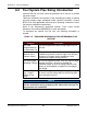
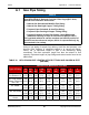
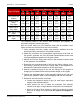
Table Of Contents
- Table of Contents
- 1. Important Safety Instructions
- 1.1 Save These Instructions
- 1.2 General Information
- 1.3 General Precautions
- 1.4 Generator Set Voltage Is Deadly
- 1.5 Engine Exhaust Is Deadly
- 1.6 Fuel and Fumes Are Flammable
- 1.7 Batteries Can Explode
- 1.8 Starting Batteries
- 1.9 Moving Parts Can Cause Severe Personal Injury or Death
- 1.10 The Hazards of Carbon Monoxide
- 2. Introduction
- 3. Pre-Installation Considerations
- 4. Installation
- 5. Startup and Configuration
- 5.1 "Establishing Communications" Message
- 5.2 "Clock Setup" Screen
- 5.3 "Exercise" Screen
- 5.4 "Brightness and Contrast" Screen
- 5.5 "About" Screen
- 5.6 "Event Log" Screen
- 5.7 "Fault Log" Screen
- 5.8 "System Status" Screen
- 5.9 "Mode" Screen
- 5.10 Automatic Load Management
- 5.11 Manual Start Sequence (Local)
- 5.12 Checklist
- 5.13 Startup
- 6. Remote Monitoring System (RMS) Description
- Appendix A. Fuel Line Selection
- Appendix B. Outline and System Drawings
- Appendix C. Wiring Diagrams

Appendix A. Fuel Line Selection 8-2019
84 A062J678 (Issue 2)Copyright © 2019 Cummins Inc.
A.0 Fuel System Pipe Sizing Introduction
Incorrect fuel line size may cause the generator set to not run or provide
full power output.
Tables are included in this section to help calculate pipe sizing for natural
gas and propane vapor withdrawal under specified conditions. Consult
NFPA 54 or other applicable codes for other operating conditions or other
fuel system installation requirements.
Refer to the Engineering Application Manual T-030: Liquid Cooled
Generator Sets manual (A040S369) for more information.
To determine the optimal fuel line size, the following information is
needed:
TABLE 16. REQUIRED INFORMATION FOR DETERMINING FUEL
LINE SIZE
Category Description
Fuel Flow
Requirements for
the Generator Set
Fuel flow requirements have a large impact on fuel
line size.
Fuel Source
(Natural Gas or
Propane Vapor)
Fuel sources can affect fuel line size. Natural gas
installations generally require a higher fuel flow rate
compared to propane vapor installations, since
propane has a higher energy content.
Fuel Line Length
(Including Fittings)
As fuel line lengths increase, they may require larger
diameter fuel lines. Be sure to consider the
equivalent length of all of the fittings (elbows, tees,
valves) in the installation in addition to the straight
pipe length.
Fuel Line Type
(e.g., Copper
Tubing or Iron
Pipe)
Most fuel line types are iron pipe or copper tubing.
Be sure to use the sizing chart for the fuel line type
when sizing the fuel line.
NOTICE
NFPA 54 has selection tables for other approved fuel lines. Verify
with the authorities having jurisdiction the allowed fuel line type for
the generator set installation.