
Install Manual
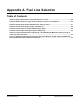
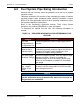
Table Of Contents
- Table of Contents
- 1. Important Safety Instructions
- 1.1 Save These Instructions
- 1.2 General Information
- 1.3 General Precautions
- 1.4 Generator Set Voltage Is Deadly
- 1.5 Engine Exhaust Is Deadly
- 1.6 Fuel and Fumes Are Flammable
- 1.7 Batteries Can Explode
- 1.8 Starting Batteries
- 1.9 Moving Parts Can Cause Severe Personal Injury or Death
- 1.10 The Hazards of Carbon Monoxide
- 2. Introduction
- 3. Pre-Installation Considerations
- 4. Installation
- 5. Startup and Configuration
- 5.1 "Establishing Communications" Message
- 5.2 "Clock Setup" Screen
- 5.3 "Exercise" Screen
- 5.4 "Brightness and Contrast" Screen
- 5.5 "About" Screen
- 5.6 "Event Log" Screen
- 5.7 "Fault Log" Screen
- 5.8 "System Status" Screen
- 5.9 "Mode" Screen
- 5.10 Automatic Load Management
- 5.11 Manual Start Sequence (Local)
- 5.12 Checklist
- 5.13 Startup
- 6. Remote Monitoring System (RMS) Description
- Appendix A. Fuel Line Selection
- Appendix B. Outline and System Drawings
- Appendix C. Wiring Diagrams

83A062J678 (Issue 2) Copyright © 2019 Cummins Inc.
Appendix A. Fuel Line Selection
Table of Contents
Table 16. Required Information for Determining Fuel Line Size ............................................................. 84
Table 18. NFPA Equivalent Lengths of Pipe Fittings and Valves in Feet (Meters) ................................ 85
Table 20. Natural Gas Schedule 40 Metallic Pipe Sizing in Inches ......................................................... 87
Table 23. Natural Gas Semirigid Copper Tubing Sizing ........................................................................... 88
Table 26. Propane Vapor Schedule 40 Metallic Pipe Sizing .................................................................... 90
Table 29. Propane Vapor Semirigid Copper Tubing Sizing ..................................................................... 92
Table 32. Propane Schedule 40 Iron Pipe Sizing, Liquid Withdrawal (Maximum Capacity of Pipe in
Cubic Feet of Gas per Hour)* ...................................................................................................................... 93
Figure 37. Minimum LPG Tank Size (50% Full) Required to Maintain 5 PSIG at Specific Withdrawal
Rate and Minimum Expected Winter Temperature ................................................................................... 95