
Install Manual
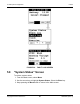
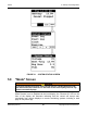
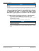
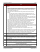
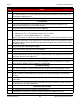
Table Of Contents
- Table of Contents
- 1. Important Safety Instructions
- 1.1 Save These Instructions
- 1.2 General Information
- 1.3 General Precautions
- 1.4 Generator Set Voltage Is Deadly
- 1.5 Engine Exhaust Is Deadly
- 1.6 Fuel and Fumes Are Flammable
- 1.7 Batteries Can Explode
- 1.8 Starting Batteries
- 1.9 Moving Parts Can Cause Severe Personal Injury or Death
- 1.10 The Hazards of Carbon Monoxide
- 2. Introduction
- 3. Pre-Installation Considerations
- 4. Installation
- 5. Startup and Configuration
- 5.1 "Establishing Communications" Message
- 5.2 "Clock Setup" Screen
- 5.3 "Exercise" Screen
- 5.4 "Brightness and Contrast" Screen
- 5.5 "About" Screen
- 5.6 "Event Log" Screen
- 5.7 "Fault Log" Screen
- 5.8 "System Status" Screen
- 5.9 "Mode" Screen
- 5.10 Automatic Load Management
- 5.11 Manual Start Sequence (Local)
- 5.12 Checklist
- 5.13 Startup
- 6. Remote Monitoring System (RMS) Description
- Appendix A. Fuel Line Selection
- Appendix B. Outline and System Drawings
- Appendix C. Wiring Diagrams

5. Startup and Configuration8-2019
75A062J678 (Issue 2) Copyright © 2019 Cummins Inc.
Tick Area
The generator set is properly supported and attached to an approved base.
The supporting base is of non-combustible material and extends 2 inches (50.8 mm)
all around the generator set.
The generator set is located to comply with applicable codes and standards.
Fuel System
Verify that the generator set is configured to the fuel being used. (See the Fuel
Selection and Fuel System Connection section.)
Verify that the fuel line has proper volume capability.
Verify that fuel pressure is correct:
• Natural gas: 3.5 - 12 inch water column (0.9 - 3.0 kPa)
• Propane: 6 - 12 inch water column (1.5 - 3.0 kPa)
Maximum pressure for either fuel under any condition: 13 inch water column (3.2 kPa)
Verify the fuel pressure at the generator set connection does not drop below the range
listed above during startup and full load operation and does not exceed 13 inch water
column (3.2 kPa).
Verify that all fuel connections are tight.
Verify there are no gas leaks in the fuel system.
All electrical and fuel lines are properly separated.
An approved flexible fuel line is properly installed between the generator set fuel inlet
connection and the fuel supply line.
Exhaust System
All areas around the generator set are well ventilated, with no possibility of exhaust
fumes entering building doors, windows, or intake fans.
AC and DC Wiring
Wire sizes, insulation, conduits and connection methods all meet applicable codes.
All load, line and generator set connections are well made and correct.
Flexible conduit is used between the generator set and the building or surrounding
structure.
A transfer switch has been installed properly to prevent connecting the generator set
to the utility.
Verify that 120 VAC power has been provided to the power battery charger and other
AC accessories on the generator set.
Generator Set Pre-Start
The generator set engine is properly serviced with oil.
All generator set and ATS covers and safety shields are installed correctly.