
Install Manual
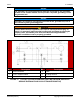
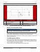
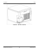
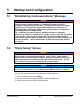
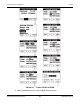
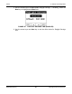
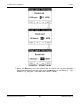
Table Of Contents
- Table of Contents
- 1. Important Safety Instructions
- 1.1 Save These Instructions
- 1.2 General Information
- 1.3 General Precautions
- 1.4 Generator Set Voltage Is Deadly
- 1.5 Engine Exhaust Is Deadly
- 1.6 Fuel and Fumes Are Flammable
- 1.7 Batteries Can Explode
- 1.8 Starting Batteries
- 1.9 Moving Parts Can Cause Severe Personal Injury or Death
- 1.10 The Hazards of Carbon Monoxide
- 2. Introduction
- 3. Pre-Installation Considerations
- 4. Installation
- 5. Startup and Configuration
- 5.1 "Establishing Communications" Message
- 5.2 "Clock Setup" Screen
- 5.3 "Exercise" Screen
- 5.4 "Brightness and Contrast" Screen
- 5.5 "About" Screen
- 5.6 "Event Log" Screen
- 5.7 "Fault Log" Screen
- 5.8 "System Status" Screen
- 5.9 "Mode" Screen
- 5.10 Automatic Load Management
- 5.11 Manual Start Sequence (Local)
- 5.12 Checklist
- 5.13 Startup
- 6. Remote Monitoring System (RMS) Description
- Appendix A. Fuel Line Selection
- Appendix B. Outline and System Drawings
- Appendix C. Wiring Diagrams

4. Installation8-2019
49A062J678 (Issue 2) Copyright © 2019 Cummins Inc.
NOTICE
The generator set grounding terminal must be connected to the grounding
terminal in the transfer switch. Do not provide a separate grounding rod for
the generator set.
NOTICE
Generator set neutral is not typically grounded at the generator set, but at
the common system grounding point.
WARNING
Contact with electrical equipment can result in severe personal injury or
death. It is extremely important that bonding and equipment grounding be
properly done. All metallic parts that could become energized under
abnormal conditions must be properly grounded.
No. Description No. Description
1 Service Entrance 4 Loads
2 2-Pole Transfer Switch 5 To Utility Service
3 Generator Set
FIGURE 18. TYPICAL SYSTEM GROUNDING ONE-LINE DIAGRAM (SEPARATE
SERVICE ENTRANCE AND 2-POLE TRANSFER SWITCH)