
Install Manual
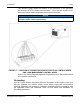
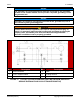
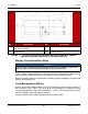
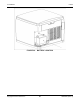
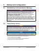
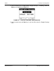
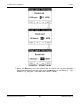
Table Of Contents
- Table of Contents
- 1. Important Safety Instructions
- 1.1 Save These Instructions
- 1.2 General Information
- 1.3 General Precautions
- 1.4 Generator Set Voltage Is Deadly
- 1.5 Engine Exhaust Is Deadly
- 1.6 Fuel and Fumes Are Flammable
- 1.7 Batteries Can Explode
- 1.8 Starting Batteries
- 1.9 Moving Parts Can Cause Severe Personal Injury or Death
- 1.10 The Hazards of Carbon Monoxide
- 2. Introduction
- 3. Pre-Installation Considerations
- 4. Installation
- 5. Startup and Configuration
- 5.1 "Establishing Communications" Message
- 5.2 "Clock Setup" Screen
- 5.3 "Exercise" Screen
- 5.4 "Brightness and Contrast" Screen
- 5.5 "About" Screen
- 5.6 "Event Log" Screen
- 5.7 "Fault Log" Screen
- 5.8 "System Status" Screen
- 5.9 "Mode" Screen
- 5.10 Automatic Load Management
- 5.11 Manual Start Sequence (Local)
- 5.12 Checklist
- 5.13 Startup
- 6. Remote Monitoring System (RMS) Description
- Appendix A. Fuel Line Selection
- Appendix B. Outline and System Drawings
- Appendix C. Wiring Diagrams

4. Installation 8-2019
48 A062J678 (Issue 2)Copyright © 2019 Cummins Inc.
The following image shows the location of the connectors in the generator
set where the ATS DC control wires terminate. This is also the location of the
connectors where load management control wires terminate.
NOTICE
Class 1 wiring methods should be used for connecting the generator
set and transfer switch signal wiring.
FIGURE 17. LOCATION OF CONNECTION POINTS FOR ATS DC CONTROL WIRES
AND LOAD MANAGEMENT CONTROL WIRES
Refer to the Wiring Diagrams appendix for generator set to RA transfer switch
DC customer connections.
Grounding
Use the Typical System Grounding One-Line Diagrams in this section to be sure
that the generator set, transfer switch, power supply wiring and all connected
electrical equipment are bonded to a common grounding point in accordance with
the applicable codes and standards. Refer to local codes and standards for
grounding procedures.