
Install Manual
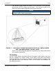
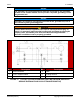
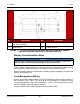
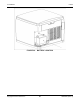
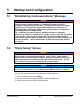
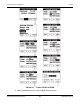
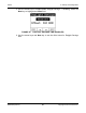
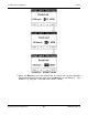
Table Of Contents
- Table of Contents
- 1. Important Safety Instructions
- 1.1 Save These Instructions
- 1.2 General Information
- 1.3 General Precautions
- 1.4 Generator Set Voltage Is Deadly
- 1.5 Engine Exhaust Is Deadly
- 1.6 Fuel and Fumes Are Flammable
- 1.7 Batteries Can Explode
- 1.8 Starting Batteries
- 1.9 Moving Parts Can Cause Severe Personal Injury or Death
- 1.10 The Hazards of Carbon Monoxide
- 2. Introduction
- 3. Pre-Installation Considerations
- 4. Installation
- 5. Startup and Configuration
- 5.1 "Establishing Communications" Message
- 5.2 "Clock Setup" Screen
- 5.3 "Exercise" Screen
- 5.4 "Brightness and Contrast" Screen
- 5.5 "About" Screen
- 5.6 "Event Log" Screen
- 5.7 "Fault Log" Screen
- 5.8 "System Status" Screen
- 5.9 "Mode" Screen
- 5.10 Automatic Load Management
- 5.11 Manual Start Sequence (Local)
- 5.12 Checklist
- 5.13 Startup
- 6. Remote Monitoring System (RMS) Description
- Appendix A. Fuel Line Selection
- Appendix B. Outline and System Drawings
- Appendix C. Wiring Diagrams

4. Installation8-2019
47A062J678 (Issue 2) Copyright © 2019 Cummins Inc.
The AC circuit must be 120 VAC, 20 Amp protected. The wires from this
customer supplied circuit are terminated within the enclosure at the five place
connectors labeled "Ground", "Line" and "Neutral". Follow regional
regulations and applicable electrical codes for installation.
FIGURE 16. CUSTOMER AC CONNECTIONS
DC Connections
NOTICE
See the Wiring Diagrams appendix for DC customer connections.
Automatic Transfer Switch (ATS) DC Connections
WARNING
Failure to use an approved transfer switch can lead to the electrocution
of personnel working on the utility lines, damage to equipment, fire, or
personal injury. An approved switching device must be used to prevent
interconnection to the public utility.
Install the transfer switch in accordance with the appropriate RA Series
Transfer Switch Owner Manual.