
Install Manual
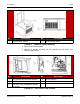
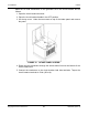
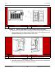
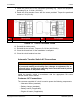
Table Of Contents
- Table of Contents
- 1. Important Safety Instructions
- 1.1 Save These Instructions
- 1.2 General Information
- 1.3 General Precautions
- 1.4 Generator Set Voltage Is Deadly
- 1.5 Engine Exhaust Is Deadly
- 1.6 Fuel and Fumes Are Flammable
- 1.7 Batteries Can Explode
- 1.8 Starting Batteries
- 1.9 Moving Parts Can Cause Severe Personal Injury or Death
- 1.10 The Hazards of Carbon Monoxide
- 2. Introduction
- 3. Pre-Installation Considerations
- 4. Installation
- 5. Startup and Configuration
- 5.1 "Establishing Communications" Message
- 5.2 "Clock Setup" Screen
- 5.3 "Exercise" Screen
- 5.4 "Brightness and Contrast" Screen
- 5.5 "About" Screen
- 5.6 "Event Log" Screen
- 5.7 "Fault Log" Screen
- 5.8 "System Status" Screen
- 5.9 "Mode" Screen
- 5.10 Automatic Load Management
- 5.11 Manual Start Sequence (Local)
- 5.12 Checklist
- 5.13 Startup
- 6. Remote Monitoring System (RMS) Description
- Appendix A. Fuel Line Selection
- Appendix B. Outline and System Drawings
- Appendix C. Wiring Diagrams

4. Installation 8-2019
46 A062J678 (Issue 2)Copyright © 2019 Cummins Inc.
8. Install the ground line to the equipment grounding lug. Torque the equipment
grounding lug to 13.6 Nm (120 in-lb).
9. Install the circuit breaker cover with the screw provided. Torque the pan-head
screw to 1.36 (12 in-lb).
No. Description No. Description
1 Provided Screw 2 Circuit Breaker Cover
FIGURE 15. CIRCUIT BREAKER COVER
10. Reinstall the intake panel.
11. Reinstall the two screws. Torque to 5–6.6 Nm (44–58 in-lb).
12. Close the lid and lock it if the installation is complete.
13. Close the circuit breaker box door.
Automatic Transfer Switch AC Connections
WARNING
Failure to use an approved transfer switch can lead to the electrocution
of personnel working on the utility lines, damage to equipment, fire, or
personal injury. An approved switching device must be used to prevent
interconnection to the public utility.
Install the transfer switch in accordance with the appropriate RA series
transfer switch owner manual.
Customer AC Connections
The customer supplied AC circuit is used to power the following components:
• Alternator heater (standard)
• Battery charger (standard)
• Battery heater (if applicable)
• Engine oil heater (if applicable)