
Install Manual
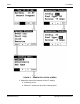
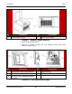
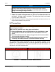
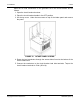
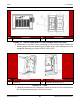
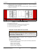
Table Of Contents
- Table of Contents
- 1. Important Safety Instructions
- 1.1 Save These Instructions
- 1.2 General Information
- 1.3 General Precautions
- 1.4 Generator Set Voltage Is Deadly
- 1.5 Engine Exhaust Is Deadly
- 1.6 Fuel and Fumes Are Flammable
- 1.7 Batteries Can Explode
- 1.8 Starting Batteries
- 1.9 Moving Parts Can Cause Severe Personal Injury or Death
- 1.10 The Hazards of Carbon Monoxide
- 2. Introduction
- 3. Pre-Installation Considerations
- 4. Installation
- 5. Startup and Configuration
- 5.1 "Establishing Communications" Message
- 5.2 "Clock Setup" Screen
- 5.3 "Exercise" Screen
- 5.4 "Brightness and Contrast" Screen
- 5.5 "About" Screen
- 5.6 "Event Log" Screen
- 5.7 "Fault Log" Screen
- 5.8 "System Status" Screen
- 5.9 "Mode" Screen
- 5.10 Automatic Load Management
- 5.11 Manual Start Sequence (Local)
- 5.12 Checklist
- 5.13 Startup
- 6. Remote Monitoring System (RMS) Description
- Appendix A. Fuel Line Selection
- Appendix B. Outline and System Drawings
- Appendix C. Wiring Diagrams

4. Installation8-2019
45A062J678 (Issue 2) Copyright © 2019 Cummins Inc.
No. Description No. Description
1 L2 2 L1
FIGURE 13. CIRCUIT BREAKER AC LOAD CONNECTIONS LOCATION
6. Unless there is no utility source connected to ATS or house loads, remove the
bonding jumper from the neutral lug on the back of the circuit breaker box to the
equipment grounding lug. Refer to NFPA 70E or CEC.
No. Description No. Description
1 Neutral Lug 2 Equipment Grounding Lug
FIGURE 14. LUGS
7. Install the neutral line to the neutral lug found on the back of the circuit breaker
box. Torque the neutral lug to 13.6 Nm (120 in-lb).