
Install Manual
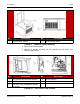
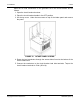
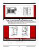
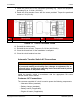
Table Of Contents
- Table of Contents
- 1. Important Safety Instructions
- 1.1 Save These Instructions
- 1.2 General Information
- 1.3 General Precautions
- 1.4 Generator Set Voltage Is Deadly
- 1.5 Engine Exhaust Is Deadly
- 1.6 Fuel and Fumes Are Flammable
- 1.7 Batteries Can Explode
- 1.8 Starting Batteries
- 1.9 Moving Parts Can Cause Severe Personal Injury or Death
- 1.10 The Hazards of Carbon Monoxide
- 2. Introduction
- 3. Pre-Installation Considerations
- 4. Installation
- 5. Startup and Configuration
- 5.1 "Establishing Communications" Message
- 5.2 "Clock Setup" Screen
- 5.3 "Exercise" Screen
- 5.4 "Brightness and Contrast" Screen
- 5.5 "About" Screen
- 5.6 "Event Log" Screen
- 5.7 "Fault Log" Screen
- 5.8 "System Status" Screen
- 5.9 "Mode" Screen
- 5.10 Automatic Load Management
- 5.11 Manual Start Sequence (Local)
- 5.12 Checklist
- 5.13 Startup
- 6. Remote Monitoring System (RMS) Description
- Appendix A. Fuel Line Selection
- Appendix B. Outline and System Drawings
- Appendix C. Wiring Diagrams

4. Installation8-2019
41A062J678 (Issue 2) Copyright © 2019 Cummins Inc.
e. Reach through the fuel selection handle access opening and turn the
handle counterclockwise until it reaches detent (90° from starting
position).
NOTICE
The handle should be horizontal for LP, vertical for NG.
f. Reinstall the fuel selector access cover. Torque screws to 5–6.6 Nm
(44–58 in-lb).
g. Reinstall the exhaust panel. Torque screws to 5–6.6 Nm (44–58 in-
lb).
h. Close the generator set cover.
Testing the Fuel System for Leaks
After assembly and before initial operation, all of the fuel system components must
be tested and proven free of any leaks.
WARNING
Fuel presents the hazard of explosion or fire which can result in severe
personal injury or death. Do not use an open flame to check for leaks. Do not
smoke or allow any flame, spark, pilot light, arc-producing equipment, switch
or other ignition sources around fuel or fuel components. Keep multi-type
ABC fire extinguishers close by.
NOTICE
Follow any local codes and standards, as they may require a different
method or documentation of a leak test.
Perform the following fuel piping system leak check:
1. After assembly and before initial operation of generator set, test all fuel system
components as required per the National Fuel Gas Code (NFPA 54).
2. The National Fuel Gas Code requires that the generator set be isolated from
the piping system by disconnecting it and capping the outlet prior to test. The
test pressure required is the greater of 1.5 times the supply pressure or 3 psi
(20.7 kPa) minimum.
3. After successfully completing the previous step, connect the generator set to
the fuel piping system.
4. To verify that all connections from the fuel piping system to the generator set
are free of leaks, conduct a bubble test using an approved leak detection
solution (or equivalent method) with the system pressure of 0.8 to 1.0 psi (5.5 to
7.0 kPa).
5. Spray the bubble solution on all of the joints.