
Install Manual
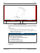
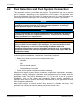
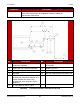
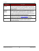
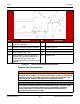
Table Of Contents
- Table of Contents
- 1. Important Safety Instructions
- 1.1 Save These Instructions
- 1.2 General Information
- 1.3 General Precautions
- 1.4 Generator Set Voltage Is Deadly
- 1.5 Engine Exhaust Is Deadly
- 1.6 Fuel and Fumes Are Flammable
- 1.7 Batteries Can Explode
- 1.8 Starting Batteries
- 1.9 Moving Parts Can Cause Severe Personal Injury or Death
- 1.10 The Hazards of Carbon Monoxide
- 2. Introduction
- 3. Pre-Installation Considerations
- 4. Installation
- 5. Startup and Configuration
- 5.1 "Establishing Communications" Message
- 5.2 "Clock Setup" Screen
- 5.3 "Exercise" Screen
- 5.4 "Brightness and Contrast" Screen
- 5.5 "About" Screen
- 5.6 "Event Log" Screen
- 5.7 "Fault Log" Screen
- 5.8 "System Status" Screen
- 5.9 "Mode" Screen
- 5.10 Automatic Load Management
- 5.11 Manual Start Sequence (Local)
- 5.12 Checklist
- 5.13 Startup
- 6. Remote Monitoring System (RMS) Description
- Appendix A. Fuel Line Selection
- Appendix B. Outline and System Drawings
- Appendix C. Wiring Diagrams

4. Installation8-2019
33A062J678 (Issue 2) Copyright © 2019 Cummins Inc.
Natural Gas Supply Line Size
See the Model Specifications section for fuel specifications (such as BTU/hr).
The natural gas supply meter may need to be exchanged for a higher capacity
meter to supply the additional gas consumed by the generator set.
To correctly size the fuel pipe, you must also take other loads operated from
the fuel supply line into consideration, such as space heating and water
heating equipment.
Use the total fuel requirement of the generator set and other connected
appliances to determine the size of the fuel supply pipe. Use the tables and
charts in the Fuel Line Selection appendix to determine the correct pipe size.
The installation site might require upgrading and repair of the gas supply
system. Schedule an upgrade or repair to minimize power and gas supply
interruptions.
Make sure the full load fuel supply pressure at the inlet to the generator set
fuel shutoff valves is set between 3.5 - 12 inch water column (0.9 - 3.0 kPa)
for all operating loads (no load to full load). Refer to the Model Specifications
section.
See the Natural Gas Fuel System section for an example of a typical natural
gas installation.
Propane Fuel System
WARNING
Fuel leaks can lead to explosive accumulations of gas. Propane sinks in air
and can accumulate inside housings, basements, and other below-grade
spaces. Prevent gas leaks and the accumulation of gaseous fuel in the event
of a leak.
NOTICE
NFPA Standard No. 58 requires all persons handling and operating propane
to be trained in proper handling and operating procedures.
TABLE 14. REQUIRED COMPONENTS IN A PROPANE VAPOR FUEL SYSTEM
Component Description
Propane Tank Make sure to identify and use the correct tank size based on fuel flow
requirements and the lowest average temperature for your region. If the
tank is sized incorrectly, the generator set could run out of fuel. Refer to
the Minimum LPG Tank Size figure in the Fuel Line Selection appendix.
Shutoff Valve Useful during installation or in the event of a leak (may be required to
meet local codes).