
Install Manual
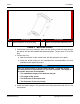
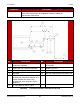
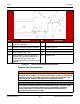
Table Of Contents
- Table of Contents
- 1. Important Safety Instructions
- 1.1 Save These Instructions
- 1.2 General Information
- 1.3 General Precautions
- 1.4 Generator Set Voltage Is Deadly
- 1.5 Engine Exhaust Is Deadly
- 1.6 Fuel and Fumes Are Flammable
- 1.7 Batteries Can Explode
- 1.8 Starting Batteries
- 1.9 Moving Parts Can Cause Severe Personal Injury or Death
- 1.10 The Hazards of Carbon Monoxide
- 2. Introduction
- 3. Pre-Installation Considerations
- 4. Installation
- 5. Startup and Configuration
- 5.1 "Establishing Communications" Message
- 5.2 "Clock Setup" Screen
- 5.3 "Exercise" Screen
- 5.4 "Brightness and Contrast" Screen
- 5.5 "About" Screen
- 5.6 "Event Log" Screen
- 5.7 "Fault Log" Screen
- 5.8 "System Status" Screen
- 5.9 "Mode" Screen
- 5.10 Automatic Load Management
- 5.11 Manual Start Sequence (Local)
- 5.12 Checklist
- 5.13 Startup
- 6. Remote Monitoring System (RMS) Description
- Appendix A. Fuel Line Selection
- Appendix B. Outline and System Drawings
- Appendix C. Wiring Diagrams

4. Installation 8-2019
32 A062J678 (Issue 2)Copyright © 2019 Cummins Inc.
Component Description
Flexible Fuel Line Protects the fuel system from vibration, expansion, and contraction. Must
meet code requirements for application and be installed per
manufacturer instructions.
No. Description No. Description
1 Distance as Required by Code and/or
Component Suppliers
7 Secondary Service Pressure Regulator
(If Required)
2 Primary Service Pressure Regulator 8 Flexible Fuel Line
3 Natural Gas Supply 9 Sediment Trap
4 Gas Meter 10 Fuel Line Connection at Generator Set
5 Note: A branch in the fuel line to the
generator set may allow selection of a
smaller diameter line size to the
generator set and remainder of gas
appliances.
11 Generator Set
6 Full Flow Manual Shutoff Valve
FIGURE 6. TYPICAL NATURAL GAS INSTALLATION