
Install Manual
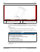
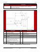
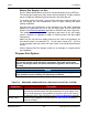
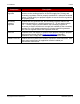
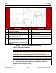
Table Of Contents
- Table of Contents
- 1. Important Safety Instructions
- 1.1 Save These Instructions
- 1.2 General Information
- 1.3 General Precautions
- 1.4 Generator Set Voltage Is Deadly
- 1.5 Engine Exhaust Is Deadly
- 1.6 Fuel and Fumes Are Flammable
- 1.7 Batteries Can Explode
- 1.8 Starting Batteries
- 1.9 Moving Parts Can Cause Severe Personal Injury or Death
- 1.10 The Hazards of Carbon Monoxide
- 2. Introduction
- 3. Pre-Installation Considerations
- 4. Installation
- 5. Startup and Configuration
- 5.1 "Establishing Communications" Message
- 5.2 "Clock Setup" Screen
- 5.3 "Exercise" Screen
- 5.4 "Brightness and Contrast" Screen
- 5.5 "About" Screen
- 5.6 "Event Log" Screen
- 5.7 "Fault Log" Screen
- 5.8 "System Status" Screen
- 5.9 "Mode" Screen
- 5.10 Automatic Load Management
- 5.11 Manual Start Sequence (Local)
- 5.12 Checklist
- 5.13 Startup
- 6. Remote Monitoring System (RMS) Description
- Appendix A. Fuel Line Selection
- Appendix B. Outline and System Drawings
- Appendix C. Wiring Diagrams

4. Installation8-2019
27A062J678 (Issue 2) Copyright © 2019 Cummins Inc.
• The generator set must be located to ensure generator intake and exhaust are
not blocked. Some examples of obstructions include grass, bushes, leaves,
walls, and fences.
• Position the generator set so that cooling air is free to enter and leave the area.
• Locate and position the generator set so that prevailing winds carry exhaust
gases and potential fuel leaks away from the house or occupied area.
See the Clearance Requirements diagram in Appendix B.
Preparing the Generator Set Mounting Surface
Cummins recommends the generator set be installed on a non-combustible
mounting pad (available as an accessory) or a poured concrete slab. The surface
beneath the mounting surface must be properly prepared to minimize the risk of the
generator set settling and causing undue stress on the fuel system or electrical
connections. The surface preparation is the same when preparing the site for
installing on the accessory mounting pad or poured slab.
Cummins recommends the generator set be installed above grade for easier
maintenance, and lower risk of submersion in water.
1. Clear obstructions and make sure that there is adequate clearance for access
to the site.
2. Ensure that the ground is stable and is not subject to flooding.
3. Level the ground, and make sure that the subgrade is compacted and settled.
Local soil condition may dictate the need for addition of sub-base and base
material layers above the subgrade. Consult with your local building officials for
requirements and recommendations for your area.
4. Either pour a concrete slab or set an accessory mounting pad on the prepared
surface. The poured concrete slab should be:
• Constructed of concrete with a 28-day compressive strength of at least
2500 psi (17,200 kPa); typical bagged concrete mix meets this requirement
• A minimum of 3 inches (76.2 mm) thick
• At least 2 inches (50.8 mm) larger in length and width than the generator
set base
5. Place the generator set on the pad and secure it to the mounting surface using
the mounting spacers (provided) and appropriate fasteners. See the Securing
the Generator Set to the Mounting Pad section for more information.
See the Clearance Requirements diagram in Appendix B.