
Install Manual
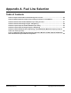
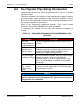
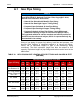
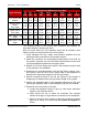
Table Of Contents
- Table of Contents
- 1. Important Safety Instructions
- 1.1 Save These Instructions
- 1.2 General Information
- 1.3 General Precautions
- 1.4 Generator Set Voltage Is Deadly
- 1.5 Engine Exhaust Is Deadly
- 1.6 Fuel and Fumes Are Flammable
- 1.7 Batteries Can Explode
- 1.8 Starting Batteries
- 1.9 Moving Parts Can Cause Severe Personal Injury or Death
- 1.10 The Hazards of Carbon Monoxide
- 2. Introduction
- 3. Pre-Installation Considerations
- 4. Installation
- 5. Startup and Configuration
- 5.1 "Establishing Communications" Message
- 5.2 "Clock Setup" Screen
- 5.3 "Exercise" Screen
- 5.4 "Brightness and Contrast" Screen
- 5.5 "About" Screen
- 5.6 "Event Log" Screen
- 5.7 "Fault Log" Screen
- 5.8 "System Status" Screen
- 5.9 "Mode" Screen
- 5.10 Automatic Load Management
- 5.11 Manual Start Sequence (Local)
- 5.12 Checklist
- 5.13 Startup
- 6. Remote Monitoring System (RMS) Description
- Appendix A. Fuel Line Selection
- Appendix B. Outline and System Drawings
- Appendix C. Wiring Diagrams

Appendix A. Fuel Line Selection 8-2019
86 A062J678 (Issue 2)Copyright © 2019 Cummins Inc.
Type of Fitting
Nominal Inch (Millimeters) Pipe Size
1/2
(15)
3/4
(20)
1
(25)
1-1/4
(32)
1-1/2
(40)
2
(50)
2-1/2
(65)
3
(80)
4
(100)
Foot Valve and
Strainer
3.7
(1.1)
4.9
(1.5)
7.5
(2.3)
8.9
(2.7)
11.0
(3.4)
15.0
(4.6)
18.0
(5.5)
22.0
(6.7)
29.0
(8.8)
Swing Check
Valve,
Fully Open
6.0
(1.8)
8.0
(2.4)
10.0
(3.0)
14.0
(4.3)
16.0
(4.9)
20.0
(6.1)
25.0
(7.6)
30.0
(9.1)
40.0
(12.2)
Globe Valve,
Fully Open
18.0
(5.5)
22.0
(6.7)
29.0
(8.8)
38.0
(11.6)
43.0
(13.1)
55.0
(16.8)
69.0
(21.0)
84.0
(25.6)
120.0
(36.6)
Angle Valve, Fully
Open
7.0
(2.1)
9.0
(2.7)
12.0
(3.7)
15.0
(4.6)
18.0
(5.5)
24.0
(7.3)
29.0
(8.8)
35.0
(10.7)
47.0
(14.3)
Gate Valve, Fully
Open
0.7
(0.2)
0.9
(0.3)
1.0
(0.3)
1.5
(0.5)
1.8
(0.5)
2.3
(0.7)
2.8
(0.9)
3.2
(1.0)
4.5
(1.4)
The remaining tables in this section show maximum gas capacity for
equivalent lengths of various pipe sizes.
Here are some basic but very important steps that all installers must
follow to make sure that fuel lines are sized correctly:
1. Verify adequate fuel flow, quality, and pressure available from the
natural gas utility connection or the propane system.
2. Obtain the maximum fuel consumption requirements at full load for
the specific generator set from the Model Specifications section and
for all gas appliances attached to the pipe system.
3. Make a list of all the fittings and valves in the proposed system used
in this generator set installation.
4. Determine the equivalent length of all fuel line fittings (elbows, tees,
and valves). (See the NFPA Pipe Fittings table in this appendix to
determine the equivalent lengths for all fuel line fittings.)
5. Add the equivalent length of the fuel line fittings to the lengths of
straight pipe to determine the total equivalent length of the system.
6. Choose the applicable table in this appendix based on the fuel type
(natural gas, propane vapor or liquid propane) and fuel line material.
7. Determine the fuel line size at full load:
a. Locate the equivalent length of pipe (or next larger equivalent
length) in the left hand column.
b. Move across the row to where the maximum flow capacity
number is as large or larger than the maximum fuel consumption.
c. Move to the top of that column to where the minimum nominal
pipe size or tubing size required for the system as designed is
shown.