
Install Manual
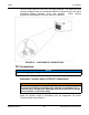
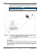
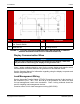
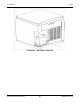
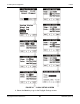
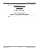
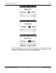
Table Of Contents
- Table of Contents
- 1. Important Safety Instructions
- 1.1 Save These Instructions
- 1.2 General Information
- 1.3 General Precautions
- 1.4 Generator Set Voltage Is Deadly
- 1.5 Engine Exhaust Is Deadly
- 1.6 Fuel and Fumes Are Flammable
- 1.7 Batteries Can Explode
- 1.8 Starting Batteries
- 1.9 Moving Parts Can Cause Severe Personal Injury or Death
- 1.10 The Hazards of Carbon Monoxide
- 2. Introduction
- 3. Pre-Installation Considerations
- 4. Installation
- 5. Startup and Configuration
- 5.1 "Establishing Communications" Message
- 5.2 "Clock Setup" Screen
- 5.3 "Exercise" Screen
- 5.4 "Brightness and Contrast" Screen
- 5.5 "About" Screen
- 5.6 "Event Log" Screen
- 5.7 "Fault Log" Screen
- 5.8 "System Status" Screen
- 5.9 "Mode" Screen
- 5.10 Automatic Load Management
- 5.11 Manual Start Sequence (Local)
- 5.12 Checklist
- 5.13 Startup
- 6. Remote Monitoring System (RMS) Description
- Appendix A. Fuel Line Selection
- Appendix B. Outline and System Drawings
- Appendix C. Wiring Diagrams

4. Installation 8-2019
50 A062J678 (Issue 2)Copyright © 2019 Cummins Inc.
No. Description No. Description
1 Combined Service Entrance and 2-
Pole Transfer Switch
3 Loads
2 Generator Set 4 To Utility Service
FIGURE 19. TYPICAL SYSTEM GROUNDING ONE-LINE DIAGRAM (COMBINED
SERVICE ENTRANCE AND 2-POLE TRANSFER SWITCH)
Display Communication Wires
NOTICE
There are two unmarked connectors on the back of the display, either one
may be used for connecting the display to the generator set.
Class 1 wiring methods should be used for the remote display and transfer switch
communication conductors between the generator set and transfer switch.
See the Operator Manual for information regarding using the display to operate and
monitor the generator set.
Load Management Wiring
See the Automatic Transfer Switch (ATS) DC Connections section for the location of
the connectors (TB-1, TB-2, TB-3, and TB-4) in the generator set, which are used
for load management control wire termination. Class 1 wiring methods should be
used for installing load management devices.
Cummins offers a kit for load management wiring (A051C329).