
Install Manual
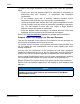
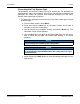
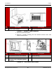
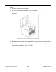
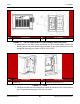
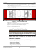
Table Of Contents
- Table of Contents
- 1. Important Safety Instructions
- 1.1 Save These Instructions
- 1.2 General Information
- 1.3 General Precautions
- 1.4 Generator Set Voltage Is Deadly
- 1.5 Engine Exhaust Is Deadly
- 1.6 Fuel and Fumes Are Flammable
- 1.7 Batteries Can Explode
- 1.8 Starting Batteries
- 1.9 Moving Parts Can Cause Severe Personal Injury or Death
- 1.10 The Hazards of Carbon Monoxide
- 2. Introduction
- 3. Pre-Installation Considerations
- 4. Installation
- 5. Startup and Configuration
- 5.1 "Establishing Communications" Message
- 5.2 "Clock Setup" Screen
- 5.3 "Exercise" Screen
- 5.4 "Brightness and Contrast" Screen
- 5.5 "About" Screen
- 5.6 "Event Log" Screen
- 5.7 "Fault Log" Screen
- 5.8 "System Status" Screen
- 5.9 "Mode" Screen
- 5.10 Automatic Load Management
- 5.11 Manual Start Sequence (Local)
- 5.12 Checklist
- 5.13 Startup
- 6. Remote Monitoring System (RMS) Description
- Appendix A. Fuel Line Selection
- Appendix B. Outline and System Drawings
- Appendix C. Wiring Diagrams

4. Installation 8-2019
44 A062J678 (Issue 2)Copyright © 2019 Cummins Inc.
Make the AC load connections to the generator set in the circuit breaker box as
follows:
1. Open the circuit breaker box door.
2. Place the circuit breaker handle in the OFF position.
3. Lift the top cover. Undo the two screws on top of the intake panel and remove
the panel.
FIGURE 12. INTAKE PANEL SCREWS
4. Route the load conductors through the access holes found at the bottom of the
circuit breaker box.
5. Connect the conductors to the circuit breaker load side terminals. Torque the
circuit breaker terminals to 5 Nm (45 in-lb).