
Install Manual
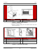
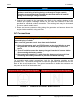
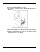
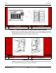
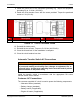
Table Of Contents
- Table of Contents
- 1. Important Safety Instructions
- 1.1 Save These Instructions
- 1.2 General Information
- 1.3 General Precautions
- 1.4 Generator Set Voltage Is Deadly
- 1.5 Engine Exhaust Is Deadly
- 1.6 Fuel and Fumes Are Flammable
- 1.7 Batteries Can Explode
- 1.8 Starting Batteries
- 1.9 Moving Parts Can Cause Severe Personal Injury or Death
- 1.10 The Hazards of Carbon Monoxide
- 2. Introduction
- 3. Pre-Installation Considerations
- 4. Installation
- 5. Startup and Configuration
- 5.1 "Establishing Communications" Message
- 5.2 "Clock Setup" Screen
- 5.3 "Exercise" Screen
- 5.4 "Brightness and Contrast" Screen
- 5.5 "About" Screen
- 5.6 "Event Log" Screen
- 5.7 "Fault Log" Screen
- 5.8 "System Status" Screen
- 5.9 "Mode" Screen
- 5.10 Automatic Load Management
- 5.11 Manual Start Sequence (Local)
- 5.12 Checklist
- 5.13 Startup
- 6. Remote Monitoring System (RMS) Description
- Appendix A. Fuel Line Selection
- Appendix B. Outline and System Drawings
- Appendix C. Wiring Diagrams

4. Installation8-2019
43A062J678 (Issue 2) Copyright © 2019 Cummins Inc.
NOTICE
Authorized installers should check local laws and jurisdictions for any
guidance restricting all wiring being run through a single conduit.
Cummins recommends that shielded wire be used where AC and DC
wiring is run through a single conduit.
2. Connect the conduit to the generator set. Refer to the outline drawing in the
Outline and System Drawings section for the size and location of the hole
provided for electrical conduit connection. The existing hole may be increased
in size to match conduit used.
3. Route and secure customer wiring along the generator set harness above the
engine intake manifold, using wire ties.
AC Connections
WARNING
Automatic startup of the generator set during installation can cause severe
personal injury or death.
Make sure the generator set is shut down and disabled:
1. Press the generator set's red STOP button on the local display to stop
the generator set. Allow the generator set to thoroughly cool to the
touch.
2. Turn off and disconnect the battery charger from the AC source before
disconnecting the battery cables.
3. Disconnect the negative (–) cable from the battery and secure it from
contacting the battery terminals to prevent accidental starting.
For grounding and neutral connections, look for the following symbols on the
generator set. The neutral connection is inside the generator set enclosure on the
back of the circuit breaker box. The ground connection is inside the enclosure on
the panel to the left of the breaker box.
Equipment Grounding Conductor Symbol Equipment Neutral Connection Symbol
FIGURE 11. SYMBOLS ON CIRCUIT BREAKER BOX