
Install Manual
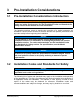
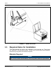
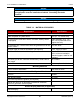
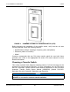
Table Of Contents
- Table of Contents
- 1. Important Safety Instructions
- 1.1 Save These Instructions
- 1.2 General Information
- 1.3 General Precautions
- 1.4 Generator Set Voltage Is Deadly
- 1.5 Engine Exhaust Is Deadly
- 1.6 Fuel and Fumes Are Flammable
- 1.7 Batteries Can Explode
- 1.8 Starting Batteries
- 1.9 Moving Parts Can Cause Severe Personal Injury or Death
- 1.10 The Hazards of Carbon Monoxide
- 2. Introduction
- 3. Pre-Installation Considerations
- 4. Installation
- 5. Startup and Configuration
- 5.1 "Establishing Communications" Message
- 5.2 "Clock Setup" Screen
- 5.3 "Exercise" Screen
- 5.4 "Brightness and Contrast" Screen
- 5.5 "About" Screen
- 5.6 "Event Log" Screen
- 5.7 "Fault Log" Screen
- 5.8 "System Status" Screen
- 5.9 "Mode" Screen
- 5.10 Automatic Load Management
- 5.11 Manual Start Sequence (Local)
- 5.12 Checklist
- 5.13 Startup
- 6. Remote Monitoring System (RMS) Description
- Appendix A. Fuel Line Selection
- Appendix B. Outline and System Drawings
- Appendix C. Wiring Diagrams

4. Installation 8-2019
26 A062J678 (Issue 2)Copyright © 2019 Cummins Inc.
Generator set location is critical for safety and performance. Follow the guidelines
below:
• The installation must comply with all applicable codes and standards (NFPA,
NEC, IBC, etc.).
• This manual only covers outdoor installations with Cummins factory installed
enclosures. This product must never be installed indoors.
• Consider access to utilities (electric meters, transfer switch, fuel supply line and
fuel tank, etc.).
• Call the local utilities to mark the locations of buried utility services (gas,
electric, telephone, etc.) before digging.
• Verify the locations of any other buried components (gas, electric telephone,
etc.) with the homeowner before digging.
• Consideration should be given to the location of sprinkler heads for irrigation
systems. The generator set should not be located where it is subjected to
substantial wetting (especially on the inlet air side) when the irrigation system is
in operation.
• Always install this generator set service regulator above the snow line.
Follow the clearance requirements below (refer to the Outline and System Drawings
appendix):
• All parts of the generator set enclosure must be at least 60 inches (1524 mm)
from any openings in walls of structures that may be occupied. Examples of
wall openings include but are not limited to: operable windows, doors, dryer
vents, fresh air intake for heaters, etc.
• The engine side and alternator side of the generator set must be located as
follows:
◦ One side (either engine or alternator) must be located not less than 18
inches (458 mm) from any structures having combustible walls. This space
must be free of any obstructions for service access.
◦ The opposite side must be located not less than 60 inches (1524 mm) from
any structures having combustible walls. A minimum of 18 inches (458
mm) of unobstructed space is required for service access.
• The intake (cooling air inlet) side of the generator set must be located not less
than 30 inches (762 mm) from any structures having combustible walls. This
space must be free of obstructions to air flow and service access.
• The generator set must be located such that exhaust gases are not able to
accumulate in an occupied area. The air discharge side must always be
unobstructed and spaced a minimum of 60 inches (1524 mm) from any
structures having combustible walls. A minimum of 36 inches (915 mm) must
be free of any combustible items, and unobstructed for service access.
• The generator set must have enough room for installation, service, and
maintenance.