
Install Manual
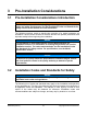
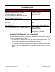
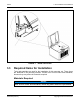
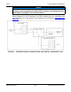
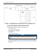
Table Of Contents
- Table of Contents
- 1. Important Safety Instructions
- 1.1 Save These Instructions
- 1.2 General Information
- 1.3 General Precautions
- 1.4 Generator Set Voltage Is Deadly
- 1.5 Engine Exhaust Is Deadly
- 1.6 Fuel and Fumes Are Flammable
- 1.7 Batteries Can Explode
- 1.8 Starting Batteries
- 1.9 Moving Parts Can Cause Severe Personal Injury or Death
- 1.10 The Hazards of Carbon Monoxide
- 2. Introduction
- 3. Pre-Installation Considerations
- 4. Installation
- 5. Startup and Configuration
- 5.1 "Establishing Communications" Message
- 5.2 "Clock Setup" Screen
- 5.3 "Exercise" Screen
- 5.4 "Brightness and Contrast" Screen
- 5.5 "About" Screen
- 5.6 "Event Log" Screen
- 5.7 "Fault Log" Screen
- 5.8 "System Status" Screen
- 5.9 "Mode" Screen
- 5.10 Automatic Load Management
- 5.11 Manual Start Sequence (Local)
- 5.12 Checklist
- 5.13 Startup
- 6. Remote Monitoring System (RMS) Description
- Appendix A. Fuel Line Selection
- Appendix B. Outline and System Drawings
- Appendix C. Wiring Diagrams

3. Pre-Installation Considerations8-2019
23A062J678 (Issue 2) Copyright © 2019 Cummins Inc.
NOTICE
If the load exceeds the generator set rating, it may be necessary to use
Cummins’ load management kit (A051C329). Cummins' load management kit
(A051C329) only applies to air cooled products.
Wiring diagrams for all RA switches, the RSS switches that are compatible with
these generator sets, and generic 2-wire switches are contained in Appendix C on
page 103 .
FIGURE 3. TRANSFER SWITCH CONNECTIONS FOR PARTIAL COVERAGE LOAD