
Install Manual
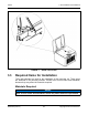
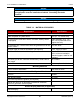
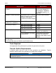
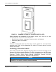
Table Of Contents
- Table of Contents
- 1. Important Safety Instructions
- 1.1 Save These Instructions
- 1.2 General Information
- 1.3 General Precautions
- 1.4 Generator Set Voltage Is Deadly
- 1.5 Engine Exhaust Is Deadly
- 1.6 Fuel and Fumes Are Flammable
- 1.7 Batteries Can Explode
- 1.8 Starting Batteries
- 1.9 Moving Parts Can Cause Severe Personal Injury or Death
- 1.10 The Hazards of Carbon Monoxide
- 2. Introduction
- 3. Pre-Installation Considerations
- 4. Installation
- 5. Startup and Configuration
- 5.1 "Establishing Communications" Message
- 5.2 "Clock Setup" Screen
- 5.3 "Exercise" Screen
- 5.4 "Brightness and Contrast" Screen
- 5.5 "About" Screen
- 5.6 "Event Log" Screen
- 5.7 "Fault Log" Screen
- 5.8 "System Status" Screen
- 5.9 "Mode" Screen
- 5.10 Automatic Load Management
- 5.11 Manual Start Sequence (Local)
- 5.12 Checklist
- 5.13 Startup
- 6. Remote Monitoring System (RMS) Description
- Appendix A. Fuel Line Selection
- Appendix B. Outline and System Drawings
- Appendix C. Wiring Diagrams

3. Pre-Installation Considerations8-2019
21A062J678 (Issue 2) Copyright © 2019 Cummins Inc.
Requirement Specification
Hardware, Cummins
provided:
Pigtail harnesses Two (one for local display and
one for remote display); 5-
wire (RS485-A
2
, RS485-B
2
,
B+, WAKEUP and B-), 1 ft
long each
Hardware, customer provided: Intermediate wires of required
length to connect to the pigtail
harnesses using splices
provided in the remote display
kit
Five wires, 600V insulation
1, 2
Wire sizes (RS485-A
2
,
RS485-B
2
, B+, WAKEUP):
Under 1000 ft wire length 20-14 AWG
Wire sizes (B+ and B-): Under 100 ft wire length 18 AWG
Under 200 ft wire length 16 AWG
Under 300 ft wire length 14 AWG
Hardware, Miscellaneous If wires can be concealed in a
wall cavity:
3 wall anchors and screws
(number 6 or number 8)
If wires cannot be concealed
in a wall cavity:
3 wall anchors and screws
(number 6 or number 8),
standoffs, and conduit or wire
raceway
1
300V insulation is acceptable for Ethernet and DC cables if routed in a separate conduit
from AC wiring.
2
Use twisted pair wires for RS485-A and RS485-B wires.
Tools Required
Use appropriate lifting techniques to position the generator set in place.
Transfer Switch Requirements
A transfer switch must be a part of every generator set installation. Transfer
switches transfer loads to the generator set during power outages.
NOTICE
Cummins offers a variety of transfer switches, including residential and light
commercial options.