Installation Manual Generator Set for Home Standby C13N6H (Spec B) C17N6H (Spec B) C20N6H (Spec B) C20N6HC (Spec B) English Original Instructions 8-2019 A062J678 (Issue 2)
Table of Contents 1. IMPORTANT SAFETY INSTRUCTIONS ....................................................................................... 1.1 Save These Instructions ........................................................................................................ 1.2 General Information ................................................................................................................ 1.3 General Precautions ...............................................................................
Table of Contents 8-2019 5.13 Startup ............................................................................................................................... 76 6. REMOTE MONITORING SYSTEM (RMS) DESCRIPTION......................................................... 6.1 Introduction .......................................................................................................................... 6.2 RMS Customer Account Setup and Generator Set Control Connection ............................
1 Important Safety Instructions 1.1 Save These Instructions This manual contains important instructions for the generator set that should be followed during installation, operation and maintenance of the generator set and batteries. Thoroughly read the operator manual before operating the generator set. Safe operation and top performance can only be obtained when equipment is properly operated and maintained.
1. Important Safety Instructions 8-2019 • Keep the generator set and its compartment clean. Do not store any items in the generator set compartment. • Before working on the generator set, make sure the generator set is shut down and disabled. 1. Press the generator set's "O" (Off) button or the red STOP button on the local display (whichever is applicable) to stop the generator set. Allow the generator set to thoroughly cool to the touch. 2.
8-2019 1. Important Safety Instructions WARNING Electrical Generating Equipment Faulty electrical generating equipment can cause severe personal injury or death. Generator sets must be installed, certified, and operated by trained and experienced persons in accordance with the installation instructions and all applicable codes. WARNING Moving Parts Moving parts can cause severe personal injury. Use extreme caution around moving parts. All guards must be properly fastened to prevent unintended contact.
1. Important Safety Instructions 8-2019 WARNING Hot Surfaces Contact with hot surfaces can cause severe burns. The unit is to be installed so that the risk of hot surface contact by people is minimized. Wear appropriate PPE when working on hot equipment and avoid contact with hot surfaces. WARNING Combustible Liquid Ignition of combustible liquids is a fire or explosion hazard which can cause severe burns or death. Do not store fuel, cleaners, oil, etc., near the generator set.
8-2019 1. Important Safety Instructions NOTICE Keep multi-type ABC fire extinguishers close by. Class A fires involve ordinary combustible materials such as wood and cloth. Class B fires involve combustible and flammable liquid fuels and gaseous fuels. Class C fires involve live electrical equipment. (Refer to NFPA No. 10 in the applicable region.) NOTICE Before performing maintenance and service procedures on enclosed generator sets, make sure the service access doors are secured open.
1. Important Safety Instructions 1.6 8-2019 Fuel and Fumes Are Flammable Fire, explosion, and personal injury or death can result from improper practices. • DO NOT permit any flame, cigarette, pilot light, spark, arcing equipment, or other ignition source near the generator set or fuel system. • Fuel lines must be adequately secured and free of leaks. Fuel connection at the engine should be made with an approved flexible line.
8-2019 1. Important Safety Instructions • To prevent arcing when disconnecting the battery: 1. Press the Off switch from the display and then press the E-Stop button (if equipped). 2. Disconnect AC power from any battery chargers. 3. Remove the negative (-) battery cables to prevent starting. • To prevent arcing when reconnecting the battery: 1. Reconnect the positive (+) cables. 2. Reconnect the negative (-) cables. 3. Reconnect the battery charger to AC power supply.
1. Important Safety Instructions 8-2019 1.10 The Hazards of Carbon Monoxide Carbon monoxide (CO) is an odorless, colorless, tasteless and non-irritating gas. You cannot see it or smell it. Red blood cells, however, have a greater affinity for CO than for oxygen. Therefore, exposure even to low levels of CO for a prolonged period can lead to asphyxiation (lack of oxygen) resulting in death.
2 Introduction 2.1 About This Manual WARNING Improper installation can result in severe personal injury, death and damage to equipment. The installation must comply with all applicable building codes (including project permits and inspections). The installer should be properly trained and licensed to perform electrical and mechanical equipment installations (including gaseous fuel installation). NOTICE Manuals are updated from time to time to reflect changes in the equipment and its specifications.
2. Introduction 8-2019 Abbr. Description Abbr.
8-2019 2. Introduction Abbr. 2.3 Description Abbr.
2. Introduction 8-2019 NOTICE A generator set must be operated and maintained properly if you are to expect safe and reliable operation. The Operator manual includes a maintenance schedule and a troubleshooting guide. The Health and Safety manual must be read in conjunction with this manual for the safe operation of the generator set, as well as the Warranty Statements.
8-2019 2. Introduction 2.4 Model Specifications TABLE 1. MODEL VARIATIONS Model Natural Gas or Propane Vapor kW Amps C13N6H Both 13 54.2 C17N6H Both 17 70.8 Natural Gas Only 18 75 Propane Vapor Only 20 83.3 C20N6H, C20N6HC Frequency Voltage 60 Hz 120/240 VAC Single Phase NOTICE Maximum load imbalance allowed is 50% of generator set rating. TABLE 2.
2. Introduction 8-2019 TABLE 4. ENGINE SPECIFICATIONS Type Value Engine 2 cylinder v-twin, OHV, air-cooled, 4-stroke, spark ignited Displacement 999 cc (60.9 in3) Spark Plug Gap 0.38–0.58 mm (0.015–0.023 in) Spark Plug Torque (Cold Engine) 25–30 Nm (18–22 ft-lb) Magneto Gap 0.25–0.35 mm (0.010–0.
8-2019 2. Introduction TABLE 7. GENERATOR SET DERATING GUIDELINES Engine Power Available Up To... Model Derate At… Elevation Ambient Temperature C13N6H 2100 m (6900 ft) 25 °C (77 °F) C17N6H 300 m (1000 ft) 25 °C (77 °F) C20N6H, C20N6HC 0 m (0 ft) 15 °C (60 °F) Elevation Temperature 3.5% per 300 m (1000 ft) 1% per 5.
2. Introduction 2.5 8-2019 Before Installation Before beginning the installation of the generator set, verify that the unit was correctly selected. Check the following features: • Model • Specifications • Options • Fuel Supply ◦ The gas supplied to the generator set must be of acceptable quality. ◦ The gas supply must have sufficient pressure. Care must be taken to be sure that the gas supply at the generator set, not just at the source, is of proper pressure for operation.
3 Pre-Installation Considerations 3.1 Pre-Installation Considerations Introduction WARNING The installer is responsible for complying with all applicable installation codes and safety requirements. See the Installation Codes and Standards for Safety section of this manual for more information. The following sections create a step-by-step overview of a typical generator set installation.
3. Pre-Installation Considerations TABLE 11.
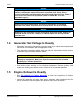
8-2019 3. Pre-Installation Considerations FIGURE 1. 3.3 HINGE LOCATION Required Items for Installation Tools and materials are used for the installation of this generator set. These items are identified in the following sections. Please refer to local codes and standards, because they may affect the materials required. Materials Required NOTICE Refer to local codes and standards, which may affect material requirements. A062J678 (Issue 2) 19 Copyright © 2019 Cummins Inc.
3. Pre-Installation Considerations 8-2019 NOTICE A UL-listed grounding electrode terminal within its ratings and suitable for the application must be installed and labeled “Grounding Electrode Terminal”. NOTICE Class 1 wiring methods must be used for connecting the generator set. TABLE 12.
8-2019 3.
3. Pre-Installation Considerations FIGURE 2. 8-2019 CUMMINS AUTOMATIC TRANSFER SWITCH (ATS) Before beginning the installation of the transfer switch, verify that the unit was correctly selected. Check the following features: • Specifications (voltage, amperage, frequency, poles, and phases) • Enclosure (indoor vs. outdoor) • Model Cummins recommends that any RA series transfer switch be used with these generator sets. Refer to the appropriate RA series ATS owner manual for more detailed information.
8-2019 3. Pre-Installation Considerations NOTICE If the load exceeds the generator set rating, it may be necessary to use Cummins’ load management kit (A051C329). Cummins' load management kit (A051C329) only applies to air cooled products. Wiring diagrams for all RA switches, the RSS switches that are compatible with these generator sets, and generic 2-wire switches are contained in Appendix C on page 103 . FIGURE 3.
3. Pre-Installation Considerations FIGURE 4. 8-2019 TRANSFER SWITCH CONNECTIONS FOR FULL COVERAGE LOAD Loose Parts Shipped with the Generator Set The following loose parts are shipped with the generator set: • Two enclosure keys • Generator set mounting spacers • Circuit breaker cover and screw • Chassis plugs • Transfer switch TB4 jumper NOTICE This jumper must be installed in the RA series transfer switch according to the interconnect diagram in the RA series transfer switch owner manual.
4 Installation 4.1 Site Assessment and Preparation Proper component location and site preparation have a very important impact on completing a successful installation.
4. Installation 8-2019 Generator set location is critical for safety and performance. Follow the guidelines below: • The installation must comply with all applicable codes and standards (NFPA, NEC, IBC, etc.). • This manual only covers outdoor installations with Cummins factory installed enclosures. This product must never be installed indoors. • Consider access to utilities (electric meters, transfer switch, fuel supply line and fuel tank, etc.).
8-2019 4. Installation • The generator set must be located to ensure generator intake and exhaust are not blocked. Some examples of obstructions include grass, bushes, leaves, walls, and fences. • Position the generator set so that cooling air is free to enter and leave the area. • Locate and position the generator set so that prevailing winds carry exhaust gases and potential fuel leaks away from the house or occupied area. See the Clearance Requirements diagram in Appendix B.
4. Installation 8-2019 Lifting and Moving the Generator Set WARNING Heavy Load The generator set is heavy. Handle with care. Dropping the generator set can cause severe personal injury or death. Use appropriate lifting techniques to move the generator set. Keep feet and hands clear when lifting the generator set. CAUTION The generator set is shipped with oil in the engine crankcase. Keep the generator set upright.
8-2019 4. Installation No. 1 Description No. Spacer Length (2.18 in [55.4 mm]) FIGURE 5. 2 Description Spacer Through-Hole Diameter (0.59 in) MOUNTING SPACER 2. Prefabricated pad only: Install the bolts with the washer under the head through the spacer and into the prefabricated pad and tighten. Torque value: 37 ft-lb (50 Nm). 3. Poured slab only: a. Mark the location for the anchor bolts with the generator set in place. b.
4. Installation 4.2 8-2019 Fuel Selection and Fuel System Connection This generator set has a convertible fuel system. The generator may run on natural gas or propane, depending on the preferences of the owner. All generator sets come preconfigured from the factory for natural gas fuel. For more information on converting the fuel system type, see Converting the Fuel System Type section. NOTICE Fuel systems must be installed by qualified service technicians.
8-2019 4. Installation NOTICE It is recommended that a shutoff valve be located near the generator set for emergency shut off or servicing the generator set. Follow applicable codes. Until the generator set is connected, cap the fuel line stub-up at the generator set to prevent dirt from entering and gas from discharging if the gas supply shutoff valve is opened accidentally. To determine the required capacity, refer to the Fuel Line Selection section.
4. Installation 8-2019 Component Flexible Fuel Line No. Description Protects the fuel system from vibration, expansion, and contraction. Must meet code requirements for application and be installed per manufacturer instructions. Description No.
8-2019 4. Installation Natural Gas Supply Line Size See the Model Specifications section for fuel specifications (such as BTU/hr). The natural gas supply meter may need to be exchanged for a higher capacity meter to supply the additional gas consumed by the generator set. To correctly size the fuel pipe, you must also take other loads operated from the fuel supply line into consideration, such as space heating and water heating equipment.
4. Installation 8-2019 Component Description Primary Pressure Regulator Located at the tank outlet, the primary regulator reduces the tank pressure to the working pressure in the fuel supply line. Primary and secondary regulators must be properly matched for a safe and functional system. Consult with your propane supplier to ensure that the regulators are properly sized.
8-2019 4. Installation No. Description No.
4. Installation 8-2019 Use clean, fresh HD-5 grade propane or equivalent product consisting of at least 90% propane. NOTICE NFPA Standard No. 58 requires all persons handling and operating propane to be trained in proper handling and operating procedures. NOTICE Commercial propane may contain more than 2.5% butane, which can result in poor fuel vaporization and low tank pressure, resulting in poor engine starting and operation in below 32 °F (O °C) temperatures.
8-2019 4. Installation To assist in the proper installation of the propane tank, follow the guidelines below. • Consult your tank and propane supplier for assistance in all aspects of determining tank size, selection of components and installation requirements. • Fit the propane tanks with a pressure reducing regulator before connection to the generator set to prevent fuel system damage.
4. Installation 8-2019 Converting the Fuel System Type The generator set leaves the factory set up for natural gas. For operation on liquid propane vapor, the generator set must be converted by configuring the generator set control for propane and manually changing the fuel valve position from natural gas to propane. 1. To change the generator set control's fuel type from natural gas to liquid propane vapor: a. From the Main screen, select Menu. b.
8-2019 4. Installation FIGURE 8. GENERATOR CONFIG SCREEN 2. Adjust the manual fuel selector to the LP setting: a. Lift the top cover. b. Remove 2 screws on top of the exhaust panel. A062J678 (Issue 2) 39 Copyright © 2019 Cummins Inc.
4. Installation No. 1 8-2019 Description No. Exhaust Panel Screws FIGURE 9. 2 Description Exhaust Panel (Rear) EXHAUST PANEL REMOVAL c. Remove the exhaust panel. d. Remove 2 screws securing the fuel selector access cover and remove access cover. No. Description No. Description 1 Fuel Selector Access Cover Screws 4 Access Opening 2 Fuel Selection Handle Access 5 Fuel Selector Valve 3 View from Face of Regulator (panels not shown) FIGURE 10. Copyright © 2019 Cummins Inc.
8-2019 4. Installation e. Reach through the fuel selection handle access opening and turn the handle counterclockwise until it reaches detent (90° from starting position). NOTICE The handle should be horizontal for LP, vertical for NG. f. Reinstall the fuel selector access cover. Torque screws to 5–6.6 Nm (44–58 in-lb). g. Reinstall the exhaust panel. Torque screws to 5–6.6 Nm (44–58 inlb). h. Close the generator set cover.
4. Installation 8-2019 6. Inspect all of the joints and monitor the line pressure. If bubbles appear, there is a leak. 7. If any leaks are found, repair the joint or replace components as needed. 8. Verify the leak has been fixed. NOTICE The leak detection solution (that is, bubble solution) must be non-corrosive and be free of ammonia and chlorine. 4.3 Engine Exhaust The exhaust system for this generator set is complete and was designed specifically for this generator set.
8-2019 4. Installation NOTICE Authorized installers should check local laws and jurisdictions for any guidance restricting all wiring being run through a single conduit. Cummins recommends that shielded wire be used where AC and DC wiring is run through a single conduit. 2. Connect the conduit to the generator set. Refer to the outline drawing in the Outline and System Drawings section for the size and location of the hole provided for electrical conduit connection.
4. Installation 8-2019 Make the AC load connections to the generator set in the circuit breaker box as follows: 1. Open the circuit breaker box door. 2. Place the circuit breaker handle in the OFF position. 3. Lift the top cover. Undo the two screws on top of the intake panel and remove the panel. FIGURE 12. INTAKE PANEL SCREWS 4. Route the load conductors through the access holes found at the bottom of the circuit breaker box. 5. Connect the conductors to the circuit breaker load side terminals.
8-2019 4. Installation No. 1 Description No. L2 2 FIGURE 13. Description L1 CIRCUIT BREAKER AC LOAD CONNECTIONS LOCATION 6. Unless there is no utility source connected to ATS or house loads, remove the bonding jumper from the neutral lug on the back of the circuit breaker box to the equipment grounding lug. Refer to NFPA 70E or CEC. No. 1 Description No. Neutral Lug 2 FIGURE 14. Description Equipment Grounding Lug LUGS 7.
4. Installation 8-2019 8. Install the ground line to the equipment grounding lug. Torque the equipment grounding lug to 13.6 Nm (120 in-lb). 9. Install the circuit breaker cover with the screw provided. Torque the pan-head screw to 1.36 (12 in-lb). No. 1 Description No. Provided Screw 2 FIGURE 15. Description Circuit Breaker Cover CIRCUIT BREAKER COVER 10. Reinstall the intake panel. 11. Reinstall the two screws. Torque to 5–6.6 Nm (44–58 in-lb). 12.
8-2019 4. Installation The AC circuit must be 120 VAC, 20 Amp protected. The wires from this customer supplied circuit are terminated within the enclosure at the five place connectors labeled "Ground", "Line" and "Neutral". Follow regional regulations and applicable electrical codes for installation. FIGURE 16. CUSTOMER AC CONNECTIONS DC Connections NOTICE See the Wiring Diagrams appendix for DC customer connections.
4. Installation 8-2019 The following image shows the location of the connectors in the generator set where the ATS DC control wires terminate. This is also the location of the connectors where load management control wires terminate. NOTICE Class 1 wiring methods should be used for connecting the generator set and transfer switch signal wiring. FIGURE 17.
8-2019 4. Installation NOTICE The generator set grounding terminal must be connected to the grounding terminal in the transfer switch. Do not provide a separate grounding rod for the generator set. NOTICE Generator set neutral is not typically grounded at the generator set, but at the common system grounding point. WARNING Contact with electrical equipment can result in severe personal injury or death. It is extremely important that bonding and equipment grounding be properly done.
4. Installation No. 8-2019 Description No. Description 1 Combined Service Entrance and 2Pole Transfer Switch 3 Loads 2 Generator Set 4 To Utility Service FIGURE 19. TYPICAL SYSTEM GROUNDING ONE-LINE DIAGRAM (COMBINED SERVICE ENTRANCE AND 2-POLE TRANSFER SWITCH) Display Communication Wires NOTICE There are two unmarked connectors on the back of the display, either one may be used for connecting the display to the generator set.
8-2019 4. Installation Battery The generator set requires a 12V battery for engine cranking and powering the electronic control system. When the generator set is running, the battery is charged from the engine-driven battery charger. When the generator set is not running, an AC powered battery charger is provided to keep the battery charged. WARNING To avoid injury, wear proper safety protection when working around batteries. Keep open flames and sparks away from the equipment.
4. Installation 8-2019 FIGURE 20. Copyright © 2019 Cummins Inc.
5 Startup and Configuration 5.1 "Establishing Communications" Message NOTICE Once the battery is connected to the generator set and any display button is pressed, the local display shows an "establishing communications" message for approximately 5 seconds. (This may take longer if the signal integrity is poor between the control and display due to a bad wire or Electro-Magnetic Interference [EMI].) Once communication is established, the display shows the HOME screen.
5. Startup and Configuration 8-2019 FIGURE 21. CLOCK SETUP SCREEN 4. Select the Next key to go to the Daylight Savings screen. Copyright © 2019 Cummins Inc.
8-2019 5. Startup and Configuration 5. Use the arrow keys to enable/disable Daylight Savings. If enabling, select the Next key to highlight the Offset field. FIGURE 22. DAYLIGHT SAVINGS TIME (ENABLED) 6. Use the arrow keys and Next key to set the offset value for Daylight Savings time. A062J678 (Issue 2) 55 Copyright © 2019 Cummins Inc.
5. Startup and Configuration 8-2019 FIGURE 23. OFFSET VALUE 7. Select the Next key to go the screen that is used to set up when Daylight Savings should start. Use the arrow keys and Next key to set Month (1 – 12), Week (0 – 5), Day (Sun – Sat) and Hour (12AM – 12PM). Copyright © 2019 Cummins Inc.
8-2019 5. Startup and Configuration FIGURE 24. DAYLIGHT SAVINGS TIME (START TIME SETUP) 8. Select the Next key to go the screen that is used to set up when Daylight Savings should end. Use the arrow keys and Next key to set Month (1 – 12), Week (0 – 5), Day (Sun – Sat) and Hour (12AM – 12PM). A062J678 (Issue 2) 57 Copyright © 2019 Cummins Inc.
5. Startup and Configuration FIGURE 25. 8-2019 DAYLIGHT SAVINGS TIME (END TIME SETUP) 9. Keep selecting the Back button to save the settings and return to the main screen. Copyright © 2019 Cummins Inc.
8-2019 5.3 5. Startup and Configuration "Exercise" Screen When installing an RA series transfer switch, follow these steps to configure the Exercise mode in the generator set's local display or remote display. NOTICE Exercise settings need to be reset whenever battery power is lost or disconnected, or the control has entered “sleep” mode. NOTICE Sleep mode is entered after 30 minutes without utility or generator set power to preserve battery energy since the battery charger will not have AC power.
5. Startup and Configuration 8-2019 • Bimonthly: will exercise the generator set on the first and third occurrence of the selected day every month • Monthly: will exercise the generator set on the first occurrence of the selected day every month • Never: will never exercise the generator set Select the Next key to go to the date and time fields. 6. Use the arrow keys to set the day and time the generator set will be exercised. Select the Next key to highlight the Exercise Now field. 7.
8-2019 5. Startup and Configuration FIGURE 26. A062J678 (Issue 2) EXERCISE SETUP SCREEN 61 Copyright © 2019 Cummins Inc.
5. Startup and Configuration 5.4 8-2019 "Brightness and Contrast" Screen To adjust the brightness and contrast of the display: 1. From the Main screen, select Menu. 2. Use the arrow keys to highlight Display Setup. Select the Enter key. 3. Use the arrow keys to set brightness and contrast for the display. 4. Keep selecting the Back button to save the settings and return to the Main screen. Copyright © 2019 Cummins Inc.
8-2019 5. Startup and Configuration FIGURE 27. A062J678 (Issue 2) BRIGHTNESS AND CONTRAST SCREEN 63 Copyright © 2019 Cummins Inc.
5. Startup and Configuration 5.5 8-2019 "About" Screen To retrieve information about the display: 1. From the Main screen, select Menu. 2. Use the arrow keys to highlight About. Select the Enter key. Copyright © 2019 Cummins Inc.
8-2019 5. Startup and Configuration FIGURE 28. A062J678 (Issue 2) ABOUT SCREEN 65 Copyright © 2019 Cummins Inc.
5. Startup and Configuration 5.6 8-2019 "Event Log" Screen To retrieve information from the Event Log: 1. From the Main screen, select Menu. 2. Use the arrow keys to highlight Event Log. Select the Enter key. 3. Use the arrow keys to navigate through the Event Log. 4. Keep pressing the Back button to return to the Main screen. FIGURE 29. Copyright © 2019 Cummins Inc.
8-2019 5.7 5. Startup and Configuration "Fault Log" Screen To retrieve information from the Fault Log: 1. From the Main screen, select Menu. 2. Use the arrow keys to highlight Fault Log. Select the Enter key. 3. Scroll through the fault log using the up and down double-arrows. Each screen provides a brief description of the fault, the fault code number, the engine hours and the time and date of the fault. NOTICE If there are no faults recorded, the “No Stored Faults" screen will appear. 4.
5. Startup and Configuration 8-2019 FIGURE 30. 5.8 FAULT LOG SCREEN "System Status" Screen To retrieve system status: 1. From the Main screen, select Menu. 2. Use the arrow keys to highlight System Status. Select the Enter key. 3. Keep pressing the Back button to return to the Main screen. Copyright © 2019 Cummins Inc.
8-2019 5. Startup and Configuration FIGURE 31. 5.9 SYSTEM STATUS SCREEN "Mode" Screen WARNING To prevent unexpected starts from remote devices, disable Remote mode and disconnect the connector on the back of the local display wired to any remote mounted displays.
5. Startup and Configuration 8-2019 NOTICE The Remote function can only be activated (that is, enabled) from the local display. When Standby is on or set to Enabled, the “Standby On” LED on the front of the display will illuminate indicating the control will start the generator set in response to a utility power outage. Standby can be turned on at the local display. It can also be enabled with a remote display, web page, or a cell phone app if Remote has already been enabled at the local display.
8-2019 5. Startup and Configuration FIGURE 32. MODE SETUP SCREEN (LOCAL DISPLAY) 2. To enable or disable the Standby mode on the REMOTE display: NOTICE Remote must be enabled before Standby mode can be changed from the Remote display. If Remote mode is not enabled, Standby will remain disabled and cannot be changed. a. From any screen, select the Mode key to get to the Mode screen. b. Use the arrow keys to enable or disable the Standby mode. c.
5. Startup and Configuration 8-2019 5.10 Automatic Load Management NOTICE The capability to automatically add or remove specific electrical loads from the generator set requires that load management devices be wired to the generator set load management outputs. When the generator set is started automatically in Standby mode due to a loss of utility or manually by the operator, the control will energize all four load management outputs, disconnecting the associated loads from AC power.
8-2019 5. Startup and Configuration 5.11 Manual Start Sequence (Local) NOTICE If the utility power supply to the generator set's utility powered battery charger is interrupted, the battery can become discharged due to parasitic loads and the generator set may not start when needed. Whenever utility power is interrupted and the generator set is not in Standby mode for any reason (fuel preservation, etc.
5. Startup and Configuration Tick 8-2019 Area Proper clearance is provided around the entire generator set for service and ventilation: • All parts of the generator set enclosure must be at least 60 inches (1524 mm) from any openings in walls of structures that may be occupied. Examples of wall openings include but are not limited to: operable windows, doors, dryer vents, fresh air intake for heaters, etc.
8-2019 5. Startup and Configuration Tick Area The generator set is properly supported and attached to an approved base. The supporting base is of non-combustible material and extends 2 inches (50.8 mm) all around the generator set. The generator set is located to comply with applicable codes and standards. Fuel System Verify that the generator set is configured to the fuel being used. (See the Fuel Selection and Fuel System Connection section.) Verify that the fuel line has proper volume capability.
5. Startup and Configuration Tick 8-2019 Area All fuel shutoff valves are operational and in the open position. The installation meets all applicable local, state, and federal codes. Control Verify that the clock, exerciser and correct fuel type are set. 5.13 Startup 1. Verify that the installation was completed correctly. 2. Read the operator manual. Perform the pre-start checks as instructed. 3. Connect the battery cables to the battery with the positive (+) cable first.
6 Remote Monitoring System (RMS) Description 6.1 Introduction The Remote Monitoring System (RMS) feature allows for in-home or remote access to your generator set through a web page or smart phone app. Using the RMS, you can start or stop the generator set, adjust the exerciser date and time, determine if utility power is available, and view the last 20 events and/or faults on the generator set.
6. Remote Monitoring System (RMS) Description 8-2019 NOTICE The following Internet browsers are compatible with this option: • Microsoft Internet Explorer® (version 9 or greater) • Apple Safari® • Google Chrome™ • Mozilla Firefox® (version 3.6 or greater) • Microsoft® Edge 6.2 RMS Customer Account Setup and Generator Set Control Connection The following instructions for setting up an account and the generator set control connection are for customers only. 1.
8-2019 6. Remote Monitoring System (RMS) Description FIGURE 35. A062J678 (Issue 2) ETHERNET CABLE ROUTING 79 Copyright © 2019 Cummins Inc.
6. Remote Monitoring System (RMS) Description FIGURE 36. 8-2019 ETHERNET PORT ON GENERATOR CONTROL 5. The ethernet cable needs to be rated for 300V if it is routed through the same conduit as the AC load cables. 6. From the control, verify that your generator set has cloud connectivity on the Cloud Info screen on the display by pressing Menu => Next => About => Next => Next. 7. From a computer device, access the Cummins ConnectCloud website by navigating to https://connectcloud.cummins.com/. 8.
8-2019 6. Remote Monitoring System (RMS) Description 11. Enter your email address. Click the Send Verification Code button. 12. Check your email for the verification code and enter it in the Verification code field. 13. Click the Verify Code button. 14. Create a new password. 15. Enter your first name and last name. 16. Click on the Create button. 17. Complete the required (*) fields on the Setup New Generator page: a. Enter the contact information for the location. b.
6. Remote Monitoring System (RMS) Description 6.3 8-2019 RMS Dealer Account Registration These instructions apply to dealers only. 1. Navigate to https://portal.powercommandcloud.com. 2. Click on the Register button. The PowerCommand Account Registration page will appear. 3. Click "Dealer" in Account Type. 4. Fill in all of the required (*) fields on the page. 5. Make sure the Distributor Code and Dealer number match the information Cummins has in the World Wide Service Provider System (WWSPS).
Appendix A. Fuel Line Selection Table of Contents Table 16. Required Information for Determining Fuel Line Size ............................................................. 84 Table 18. NFPA Equivalent Lengths of Pipe Fittings and Valves in Feet (Meters) ................................ 85 Table 20. Natural Gas Schedule 40 Metallic Pipe Sizing in Inches ......................................................... 87 Table 23. Natural Gas Semirigid Copper Tubing Sizing .........................................
Appendix A. Fuel Line Selection A.0 8-2019 Fuel System Pipe Sizing Introduction Incorrect fuel line size may cause the generator set to not run or provide full power output. Tables are included in this section to help calculate pipe sizing for natural gas and propane vapor withdrawal under specified conditions. Consult NFPA 54 or other applicable codes for other operating conditions or other fuel system installation requirements.
8-2019 Appendix A. A.1 Fuel Line Selection Gas Pipe Sizing NOTICE The following tables in this section are reprinted with permission from NFPA 54-2015, National Fuel Gas Code, Copyright © 2014, National Fire Protection Association.
Appendix A. Fuel Line Selection 8-2019 Nominal Inch (Millimeters) Pipe Size Type of Fitting 1/2 (15) 1 (25) 1-1/4 (32) 1-1/2 (40) 2 (50) 2-1/2 (65) 3 (80) 4 (100) Foot Valve and Strainer 3.7 4.9 7.5 (1.1) (1.5) (2.3) 8.9 (2.7) 11.0 (3.4) 15.0 (4.6) 18.0 (5.5) 22.0 (6.7) 29.0 (8.8) Swing Check Valve, Fully Open 6.0 8.0 10.0 (1.8) (2.4) (3.0) 14.0 (4.3) 16.0 (4.9) 20.0 (6.1) 25.0 (7.6) 30.0 (9.1) 40.0 (12.2) Globe Valve, Fully Open 18.0 22.0 29.0 (5.5) (6.7) (8.8) 38.0 (11.
8-2019 Appendix A. Fuel Line Selection TABLE 20. NATURAL GAS SCHEDULE 40 METALLIC PIPE SIZING IN INCHES Gas: Natural Inlet Pressure: Less than 2 psi Pressure Drop: 0.5 in. water column Specific Gravity: 0.6 Pipe Size Nominal: Actual ID: 1⁄2 3⁄4 1 11⁄4 11⁄2 2 21⁄2 3 4 5 6 8 10 12 0.622 0.824 1.049 1.38 1.61 2.067 2.469 3.068 4.026 5.047 6.065 7.981 10.02 11.
Appendix A.
8-2019 Appendix A.
Appendix A. Fuel Line Selection 8-2019 1,400 NA NA NA 13 19 41 73 116 241 1,500 NA NA NA 13 18 39 71 111 232 1,600 NA NA NA 13 18 38 68 108 224 1,700 NA NA NA 12 17 37 66 104 217 1,800 NA NA NA 12 17 36 64 101 210 1,900 NA NA NA 11 16 35 62 98 204 2,000 NA NA NA 11 16 34 60 95 199 NA: A flow of less than 10 cfh. Note: All table entries are rounded to 3 significant digits.
8-2019 Appendix A.
Appendix A. Fuel Line Selection 8-2019 TABLE 29. PROPANE VAPOR SEMIRIGID COPPER TUBING SIZING Gas: Undiluted Propane Inlet Pressure: 11.0 in. water column Pressure Drop: 0.5 in. water column Specific Gravity: 1.5 INTENDED USE: Tube Sizing Between Single- or Second-Stage (Low-Pressure) Regulator and Appliance Tube Size (in.) Nominal K& L: 1⁄4 3⁄8 1⁄2 5⁄8 3⁄4 1 11⁄4 11⁄2 2 Nominal ACR: 3⁄8 1⁄2 5⁄8 3⁄4 7⁄8 11⁄8 13⁄8 — — Outside: 0.375 0.5 0.625 0.75 0.875 1.125 1.375 1.
8-2019 Appendix A.
Appendix A. Fuel Line Selection Equivalent Length of Pipe (ft.) 8-2019 Schedule 40 Iron Pipe Size (in.): Nominal (Inside Diameter) 1/2 3/4 1 (0.622) (0.824) (1.049) 1 1/4 (1.38) 1 1/2 (1.61) 2 3 3 1/2 4 (2.067) (3.068) (3.548) (4.
8-2019 Appendix A. Fuel Line Selection FIGURE 37. MINIMUM LPG TANK SIZE (50% FULL) REQUIRED TO MAINTAIN 5 PSIG AT SPECIFIC WITHDRAWAL RATE AND MINIMUM EXPECTED WINTER TEMPERATURE A062J678 (Issue 2) 95 Copyright © 2019 Cummins Inc.
Appendix A. Fuel Line Selection 8-2019 This page is intentionally blank. Copyright © 2019 Cummins Inc.
Appendix B. Outline and System Drawings Table of Contents Figure 38. Generator Set Outline (Sheet 1 of 4) ........................................................................................ 99 Figure 39. Generator Set Outline (Sheet 2 of 4) ...................................................................................... 100 Figure 40. Generator Set Outline (Sheet 3 of 4) ...................................................................................... 101 Figure 41.
Appendix B. Outline and System Drawings 8-2019 The drawings included in this section are representative. For current complete information, refer to the drawing package that was shipped with the unit. Copyright © 2019 Cummins Inc.
8-2019 Appendix B. FIGURE 38. A062J678 (Issue 2) Outline and System Drawings GENERATOR SET OUTLINE (SHEET 1 OF 4) 99 Copyright © 2019 Cummins Inc.
Appendix B. Outline and System Drawings 8-2019 FIGURE 39. Copyright © 2019 Cummins Inc.
8-2019 Appendix B. FIGURE 40. A062J678 (Issue 2) Outline and System Drawings GENERATOR SET OUTLINE (SHEET 3 OF 4) 101 Copyright © 2019 Cummins Inc.
Appendix B. Outline and System Drawings 8-2019 FIGURE 41. Copyright © 2019 Cummins Inc.
Appendix C. Wiring Diagrams Table of Contents Figure 42. Wiring Diagram (Sheet 1 of 6) ................................................................................................. 105 Figure 43. Wiring Diagram (Sheet 2 of 6) ................................................................................................. 106 Figure 44. Wiring Diagram (Sheet 3 of 6) ................................................................................................. 107 Figure 45.
Appendix C. Wiring Diagrams C.0 8-2019 Wiring Diagrams The drawings included in this section are representative. For current complete information, refer to the drawing package that was shipped with the unit. Copyright © 2019 Cummins Inc.
8-2019 Appendix C. FIGURE 42. A062J678 (Issue 2) Wiring Diagrams WIRING DIAGRAM (SHEET 1 OF 6) 105 Copyright © 2019 Cummins Inc.
Appendix C. Wiring Diagrams 8-2019 FIGURE 43. Copyright © 2019 Cummins Inc.
8-2019 Appendix C. FIGURE 44. A062J678 (Issue 2) Wiring Diagrams WIRING DIAGRAM (SHEET 3 OF 6) 107 Copyright © 2019 Cummins Inc.
Appendix C. Wiring Diagrams 8-2019 FIGURE 45. Copyright © 2019 Cummins Inc.
8-2019 Appendix C. FIGURE 46. A062J678 (Issue 2) Wiring Diagrams WIRING DIAGRAM (SHEET 5 OF 6) 109 Copyright © 2019 Cummins Inc.
Appendix C. Wiring Diagrams 8-2019 FIGURE 47. Copyright © 2019 Cummins Inc.
8-2019 Appendix C. FIGURE 48. A062J678 (Issue 2) Wiring Diagrams HARNESS, GENERATOR SET ELECTRICAL (SHEET 1 OF 3) 111 Copyright © 2019 Cummins Inc.
Appendix C. Wiring Diagrams 8-2019 FIGURE 49. Copyright © 2019 Cummins Inc.
8-2019 Appendix C. FIGURE 50. A062J678 (Issue 2) Wiring Diagrams HARNESS, GENERATOR SET ELECTRICAL (SHEET 3 OF 3) 113 Copyright © 2019 Cummins Inc.
Appendix C. Wiring Diagrams 8-2019 This page is intentionally blank. Copyright © 2019 Cummins Inc.
power.cummins.com Copyright © 2019 Cummins Inc. All rights reserved. Cummins, the "C" logo, PowerCommand, AmpSentry, and InPower are trademarks of Cummins Inc. Other company, product, or service names may be trademarks or service marks of others. Specifications are subject to change without notice.