Page 9 of 11A051D263 (Issue 4) Copyright © 2017 Cummins Inc.
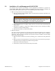
• Connect the LOAD side of the relay to the outgoing load conductors in the load center or
fuse box.
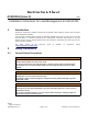
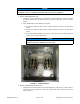
FIGURE 3. INTERCONNECTION DIAGRAM (120 VAC) (MODELS GSBA/GSBB/GSBC)
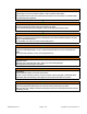
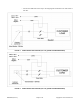
FIGURE 4. INTERCONNECTION DIAGRAM (240 VAC) (MODELS GSBA/GSBB/GSBC)