
Install Manual
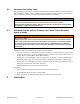
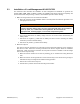

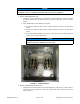

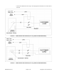
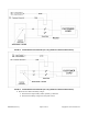
Table Of Contents

Page 8 of 11A051D263 (Issue 4) Copyright © 2017 Cummins Inc.
TABLE 1. CONNECTOR LABELS (MODELS C13N6H/C17N6H/C20N6H)
Connector Label
Load Control 1 TB1-Load Control 1
Load Control 2 TB2-Load Control 2
Load Control 3 TB3-Load Control 3
Load Control 4 TB4-Load Control 4
Ground TB7-GROUND
ii. Using 18 AWG wire for the following connections:
A. Connect a wire from the Load Control 1 connector to the "12VDC" terminal of relay
1 in the load shed device.
B. Connect a wire from the Load Control 2 connector to the "12VDC" terminal of relay
2 in the load shed device.
C. Connect wires from the Ground connector to the “COM” terminals of relays 1 and 2.
See Figure 2.
NOTICE
If only one load needs to be controlled, use only one relay. If there are two
loads that need to be controlled, use two relays.
c. Turn off the main service entrance circuit breaker or pull the fuse.
d. Remove the load center cover.
e. Make sure the load center is de-energized and associated connections are dead.
f. Using the appropriately sized wire for the load and circuit breaker size, make the following
connections (see the diagrams below for both 120 VAC and 240 VAC loads):
WARNING
Electric Shock Hazard
Voltages and currents present an electrical shock hazard that can cause severe burns
or death.
Contact with exposed energized circuits with potentials of 50 Volts AC or 75 Volts DC
or higher can cause electrical shock and electrical arc flash. Refer to standard NFPA
70E or equivalent safety standards in corresponding regions for details of the dangers
involved and for the safety requirements.
CAUTION
The following steps should only be performed by qualified personnel. Make sure that
all applicable state and local codes and regulations have been followed.
NOTICE
These relays are rated for 50A maximum; the lugs are sized for AWG #4-14, copper or
aluminum.
• Connect the output of the circuit breaker or fuse to the LINE side of the relay.