
Install Manual
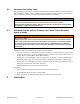
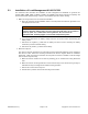

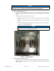

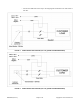
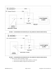
Table Of Contents

Page 7 of 11A051D263 (Issue 4) Copyright © 2017 Cummins Inc.
NOTICE
Make sure that only trained and experienced service personnel perform electrical and/or
mechanical service, in compliance with state and local codes and regulations.
a. Models GSBA/GSBB/GSBC only:
i. Identify the correct control wires for Load Control 1 and Load Control 2, which are located
in the plug and play harness that was used to connect the generator set to the transfer
switch.
ii. Using 18 AWG wire for the following connections:
A. Connect the signal wire (P7-7) to the "12VDC" terminal of relay 1 in the load shed
device.
B. Connect the signal wire (P7-8) to the "12VDC" terminal of relay 2 in the load shed
device.
C. Connect the Battery Negative (Common) or wire (P7-4) to the “COM” terminals of
relays 1 and 2. See the figure below.
NOTICE
If only one load needs to be controlled, use only one relay. If there are two
loads that need to be controlled, use two relays.
FIGURE 2. CONTACTOR BOX
b. Models C13N6H/C17N6H/C20N6H only:
i. Identify the correct terminal block connectors (Wagos) for Load Control 1, Load Control 2,
and Ground on the generator set, which are grouped with other customer DC terminal
block connectors.