
Install Manual
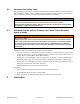
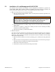


Table Of Contents

Page 5 of 11A051D263 (Issue 4) Copyright © 2017 Cummins Inc.
3.1 Installation of Load Management Kit A051C329
This instruction sheet describes the installation of load management kit A051C329 on generator set
models GSBA, GSBB, GSBC, C13N6H, C17N6H, and C20N6H. Read these instructions completely and
become familiar with safety warnings, cautions, and installation procedure before starting.
1. Make sure the generator set is shut down and disabled:
a. Place the generator set’s Run/Off/Auto switch in the Off position and allow the generator set to
thoroughly cool to the touch.
WARNING
Combustible Gases
Ignition of explosive battery gases can cause severe personal injury. Do not smoke or
cause any spark, arc, or flame while servicing batteries. Be sure to wear the
appropriate PPE, including goggles, a face shield, and protective gloves.
b. Turn off and disconnect the battery charger from the AC source before disconnecting the
battery cables.
c. Disconnect the negative (-) cable from the battery and secure it from contacting the battery
terminals to prevent accidental starting.
d. Disconnect the positive (+) cable from the battery.
2. Mount the relay box:
The relay box must be mounted to an indoor wall using the appropriate fasteners and in compliance
with all local codes. Follow the mounting instructions and see the diagram below for installation
dimensions. Make sure that the wall where the relay will be mounted is suitable to hold the weight
and size of the relay box firmly.
a. Make sure that the location has no wires or plumbing, gas, or exhaust lines running behind the
wall.
b. Make sure that the anchorage fasteners used to bolt the relay to the wall are strong enough to
withstand the relay box weight and its vibration during operation.
c. Remove the cover from the relay box.
d. Hold the box in position and mark the mounting-hole locations.