
Product Manual


7
GENSET CONTROL PANEL
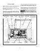
The genset control panel (Figure 3) is located be-
hind the maintenance access cover (Figure 2) and
has the following features:
Control Switch − This switch is used to prime the
fuel system, start and stop the genset and display
the fault code. Hold the switch in its START position
to crank and start the genset. Press the switch to its
STOP position to stop the genset. Hold the switch in
its STOP/PRIME position (starts in 2 seconds) to
prime the fuel system (gasoline models only). See
Troubleshooting (Page 22) about displaying fault
codes.
Status Indicator Light − This light is an LED (light
emitting diode) in the control switch which blinks
rapidly during cranking and comes on solid when
the starter disconnects, indicating that the genset is
running. If the genset shuts down abnormally, the
light will blink a code to indicate the cause of the
shutdown. See Troubleshooting (Page 22).
Line Circuit Breaker − The line circuit breaker pro-
tects the AC power leads connected to the genset
from overloads and equipment short circuits.
REMOTE CONTROL PANEL
The vehicle probably has a control panel inside the
vehicle for remote control of the genset. Onan offers
three remote control kits as follows:
• Remote switch with status indicator light only
(Figure 4).
• Remote switch with status indicator light and
hour meter (Figure 5).
• Remote switch with status indicator light and
DC voltmeter (Figure 6).
The hour meter (time totalizing meter) records gen-
set operating time in hours. It cannot be reset. See
the PERIODIC MAINTENANCE SCHEDULE
(Page 15).
The DC voltmeter indicates whether voltage across
the 12 VDC control system and battery is normal. If
the indicator consistently stays above or below the
normal zone, see MAINTAINING THE BATTERY
AND BATTERY CONNECTIONS (Page 19).
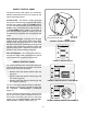
LINE CIRCUIT
BREAKERS
CONTROL SWITCH &
STATUS INDICATOR LIGHT
FIGURE 3. GENSET CONTROL PANEL
FIGURE 4. REMOTE SWITCH
FIGURE 5. REMOTE SWITCH / HOUR METER
FIGURE 6. REMOTE SWITCH / DC VOLTMETER