
Product Manual


5
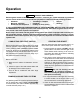
TYPICAL GENSET
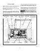
Figure 2 illustrates a typical self-enclosed genset
with the maintenance access cover removed.
Removing the access cover: Pull the top of the
cover outward and lift it away.
Securing the access cover: Catch the bottom lip
of the cover on the top edge of the base tray and
firmly push it into place.
If the cover pins and rubber grommets do not line
up, check that the edging on the top edge of the
base tray lies flat and is pushed down all the way.
If the cover feels loose, one of the rubber grommets
probably pushed through. If so, remove the cover,
insert the grommet back into its hole and try again.
CAUTION
Operating the genset with the ac-
cess cover off can lead to overheating of com-
ponents. Always secure the cover after starting
the genset.
AIR CLEANER
COVER
CIRCUIT
BREAKERS
OIL DRAIN
VALVE
(EXIT BELOW)
OIL FILL CAP &
DIPSTICK
OIL FILTER
(ACCESS BELOW)
ALTITUDE ADJUST
KNOBGASOLINE,
HGJAB, HGJAC
MAINTENANCE
ACCESS COVER
BATTERY CABLE &
REMOTE CONTROL
WIRING ENTRANCE
CONTROL SWITCH &
STATUS INDICATOR
LIGHT
RUBBER GROMMET
(1 OF 2) TO SECURE
ACCESS COVER PINS
EDGING MUST LIE
FLAT ON EDGE OF
BASE TRAY
FIGURE 2. TYPICAL SELF-ENCLOSED GENSET