
Product Manual


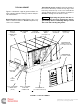

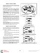
Table Of Contents

1-2
TYPICAL GENSET
Figure 1-2 illustrates a typical genset and the fea-
tures requiring attention during operation and peri-
odic maintenance.
Removing the access cover: Turn the two cover
latches counterclockwise to OPEN and pull the top
of the cover outwards.
Securing the access cover: Position the bottom of
the cover so that its lip catches the top edge of the
base tray, rotate the top of the cover towards the
genset and turn the two cover latches clockwise to
CLOSED, making sure the latches catch.
WARNING
Operating the genset with the ac-
cess cover off can lead to severe burns and en-
gine damage due to overheating. Always secure
the cover after starting the genset.
MUFFLER WITH
CLEANOUT PLUGS
(accessible from below)
AIR CLEANER
COVER
ALTITUDE
ADJUST KNOB
OIL FILL CAP
& DIPSTICK
SPARK PLUG
(not shown)
CONTROL
PANEL
(See Figure 1-3)
OIL DRAIN PLUG
(accessible from below)
MAINTENANCE
ACCESS COVER
AC
OUTPUT
LEADS
POS (+) BATTERY
CONNECTION
(inside)
NEG (−) BATTERY
& GROUND
CONNECTION
REMOTE
CONTROL
CONNECTION
(inside)
FUEL INLET
& FILTER
FIGURE 1-2. TYPICAL GENSET
Redistribution or publication of this document
by any means, is strictly prohibited.