
Product Manual

2-2
RECOMMENDED COOLANT
Use the best quality ethylene glycol antifreeze solu-
tion available. It should be fully formulated with rust
inhibitors and coolant stabilizers and mixed with
fresh (distilled) water that is low in minerals and cor-
rosive chemicals. A 50/50 mixture is recommended-
for all climates and is suitable for temperatures
down to -34
° F (-37° C).
See Section 5. Specifications for coolant capacity.
STARTING BATTERIES
The genset requires a 12 volt battery to power its
control and starting circuits. Reliable genset starting
and starter service life depend upon adequate bat-
tery system capacity and maintenance.
See MAINTAINING THE BATTERY AND BATTERY
CONNECTIONS (p. 3-4) and Section 5. Specifi-
cations for minimum required battery ratings.
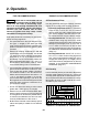
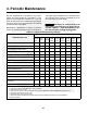
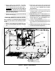
CONTROL PANEL
The control panel (Figure 2-2) has the following fea-
tures:
Control Switch − This switch is used to start and
stop the genset, prime the engine fuel system and
restore the fault code (blinking status light).
Status Lamp − This is a lamp in the control switch
that blinks rapidly during preheat and cranking. It
stays on continuously while the genset is running. If
the genset shuts down, it will blink a numerical code
to indicate the nature of the fault shutdown (see
Section 4. Troubleshooting).
(Rapid blinking before cranking starts indicates that
the glow plugs are preheating the combustion
chambers. The genset controller automatically var-
ies the time based on engine temperature.)
Line Circuit Breaker(s) − The line circuit breakers
protect the AC power leads connected to the gen-
set.
Coolant Recovery Tank Fill Cap − The recovery
tank provides for coolant expansion. Replenish the
normal loss of coolant by filling here.
Hour Meter − The hour meter records the total run-
ning time of the genset. It cannot be reset.
REMOTE CONTROL PANEL
There probably is a remote genset control panel in-
side the vehicle. Three control panel kits are avail-
able:
• Remote switch / status lamp
• Remote switch / status lamp and hour meter
• Remote switch / status lamp and DC voltmeter
The DC voltmeter indicates whether voltage across
the 12 VDC control system and battery is normal. If
the indicator consistently stays above or below the
normal zone, see MAINTAINING THE BATTERY
AND BATTERY CONNECTIONS (p. 3-4).