
Product Manual

1-4
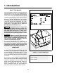
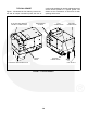
TYPICAL GENSET
Figure 1-4 illustrates the fuel, battery, remote con-
trol and AC output connection points, the flow of
cooling and ventilating air and the maintenance and
service access panels of a typical genset. Not
shown are the combustion air inlet and oil drain
openings in the base.
COOLING & VENTILATING AIR IN HOT AIR OUT
EXHAUST
CONNECTIONS
CONTROL
PANEL
FUEL
CONNECTIONS
BATTERY
CONNECTIONS
MAINTENANCE
ACCESS
AC OUTPUT AND REMOTE
CONTROL CONNECTIONS
FIGURE 1-4. TYPICAL GENSET