
Specifications


Chapter
Heading
7
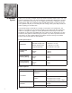
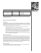
To Bottom Of RO Cartridge
Aqua-Cleer Faucet
Monitor Sensor
Monitor
Ball Valve
Tank
Drain
Drain Line
from Air Gap
to Drain (3/8” Tubing)
Cold Water Supply
Post Filter
3/8” Tubing to
Faucet Product Port
1/4” Drain Line
to Air Gap in
Faucet
Feedline 1/4” Tubing
Aqua-Cleer Manifold
Drain Connection
Note: Install the drain line so that it runs downward with no loops or low spots. Otherwise the unit will
overflow at the air gap siphon break built into the faucet, or make irritating gurgling sounds. The 1/4”
concentrate line that leads to the faucet should be installed in a straight vertical path to avoid making
a gurgling noise. For installations in Massachusetts: Massachusetts Plumbing Code 248 CMR
shall be adhered to. Consult your licensed plumber for installation of this system. The use of
saddle valves is not permitted in Massachusetts.
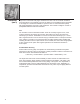
This owner’s guide provides visual assembly reference only. Since specialized
skills are required in the assembly of the drinking water system, we recommend
that you contact your local independently operated Culligan dealer to complete this
installation.
Select Component Installation Locations
Dispenser Faucet
The Culligan® faucet is designed to be mounted on the rear lip of the sink. It may
be installed in an existing sprayer attachment hole or in a hole drilled at the time of
installation. It may also be mounted to an adjacent counter top. It should be positioned
so that water is dispensed over the sink. A minimum 1-1/4” diameter hole is required.
When installing the Aqua-Cleer® water quality monitor, refer to the installation instructions
packaged with the monitor. Make certain the TDS level and/or gallons setting correspond
to the desired water supply.
Installation