
- Motorola Digital Return Transmitter Installation Sheet


Table Of Contents
- Installation Sheet
- Related Documentation
- Document Conventions
- Before You Begin
- Installing the SG2-DRT-3X in the SG2440 Node
- Installing the SG2-DRT-3X in the SG2440 Node in a 1X or 2X Configuration
- Installing the SG2-DRT-3X in the SG2000 Node
- Installing the SG2-DRT-3X in the SG2000 Node in a 1X or 2X Configuration
- Specifications
- SG2-DRT-3X DWDM Models
- SG2-DRT-3X CWDM Models
- If You Need Help
- Caution/Compliance
- Declarations of Conformity
- Copyright
- Back Cover
4 STARLINE
SG2-DRT-3X Installation Sheet
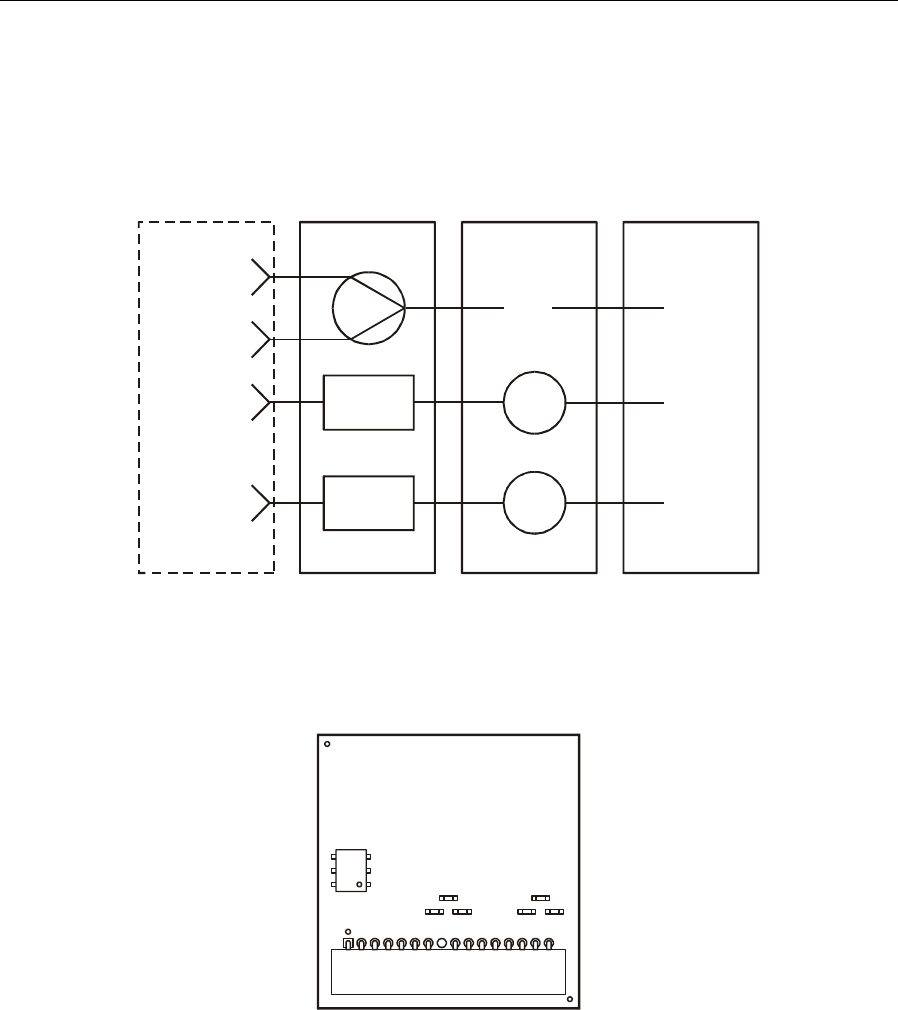
Figure 3 illustrates a block diagram of the SG2440-DR-3X return configuration:
Figure 3
SG2440-DR-3X return configuration
RP1
DRT1
DRT2
RP3
RP2
RP4
3.5 dB
3.5 dB
(MCX)
(MCX)
PLUG-IN
BOARD
E-PACK LID
TX
D sub location
DRT1
DRT2
XMTR
INPUT
C
A
B
Figure 4 illustrates the SG2440-DR-3X return board:
Figure 4
SG2440-DR-3X return board
T1
R5
R1 R2
J9
R6
R4R3