
- Motorola Digital Return Transmitter Installation Sheet


Table Of Contents
- Installation Sheet
- Related Documentation
- Document Conventions
- Before You Begin
- Installing the SG2-DRT-3X in the SG2440 Node
- Installing the SG2-DRT-3X in the SG2440 Node in a 1X or 2X Configuration
- Installing the SG2-DRT-3X in the SG2000 Node
- Installing the SG2-DRT-3X in the SG2000 Node in a 1X or 2X Configuration
- Specifications
- SG2-DRT-3X DWDM Models
- SG2-DRT-3X CWDM Models
- If You Need Help
- Caution/Compliance
- Declarations of Conformity
- Copyright
- Back Cover
2 STARLINE
SG2-DRT-3X Installation Sheet
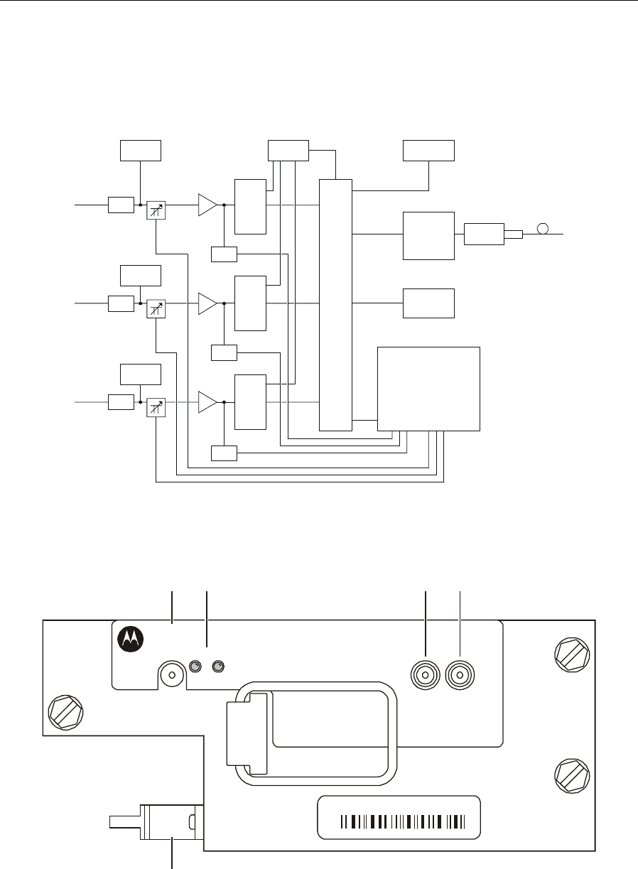
Figure 1 illustrates a block diagram of the SG2-DRT-3X:
Figure 1
SG2-DRT-3X block diagram
42 MHz
LPF
Gain
block
Gain
block
Gain
block
Pin
attenuator
Pin
attenuator
Pin
attenuator
42 MHz
LPF
42 MHz
LPF
5-42 MHz
5-42 MHz
5-42 MHz
LF pilot
generator
LF pilot
generator
LF pilot
generator
Frame
synchronization
A/D
converter
32:1
multi-
plexer
3.1 GHz
xoscillator
Laser
driver
ITU laser
Microprocessor
ADC in DAC out
A/D
converter
A/D
converter
Filt er and
clock driver
RF
detector
RF
detector
RF
detector
Figure 2 illustrates the SG2-DRT-3X:
Figure 2
SG2-DRT-3X transmitter
OPTICAL
POWER
(1 V/mW)
I
N
P
U
T
I
N
P
U
T
AB
SG2-DRT-3X
Digital Return Optical Transmitter
ALARM
F
A
U
L
T
O
N
1324
5
XXXXXX-XXX-XX
XXXXXXXXXXX
ITU/CH XX WAV XXXX.XX