
- Motorola Digital Return Transmitter Installation Sheet


Table Of Contents
- Installation Sheet
- Related Documentation
- Document Conventions
- Before You Begin
- Installing the SG2-DRT-3X in the SG2440 Node
- Installing the SG2-DRT-3X in the SG2440 Node in a 1X or 2X Configuration
- Installing the SG2-DRT-3X in the SG2000 Node
- Installing the SG2-DRT-3X in the SG2000 Node in a 1X or 2X Configuration
- Specifications
- SG2-DRT-3X DWDM Models
- SG2-DRT-3X CWDM Models
- If You Need Help
- Caution/Compliance
- Declarations of Conformity
- Copyright
- Back Cover
10 STARLINE
SG2-DRT-3X Installation Sheet
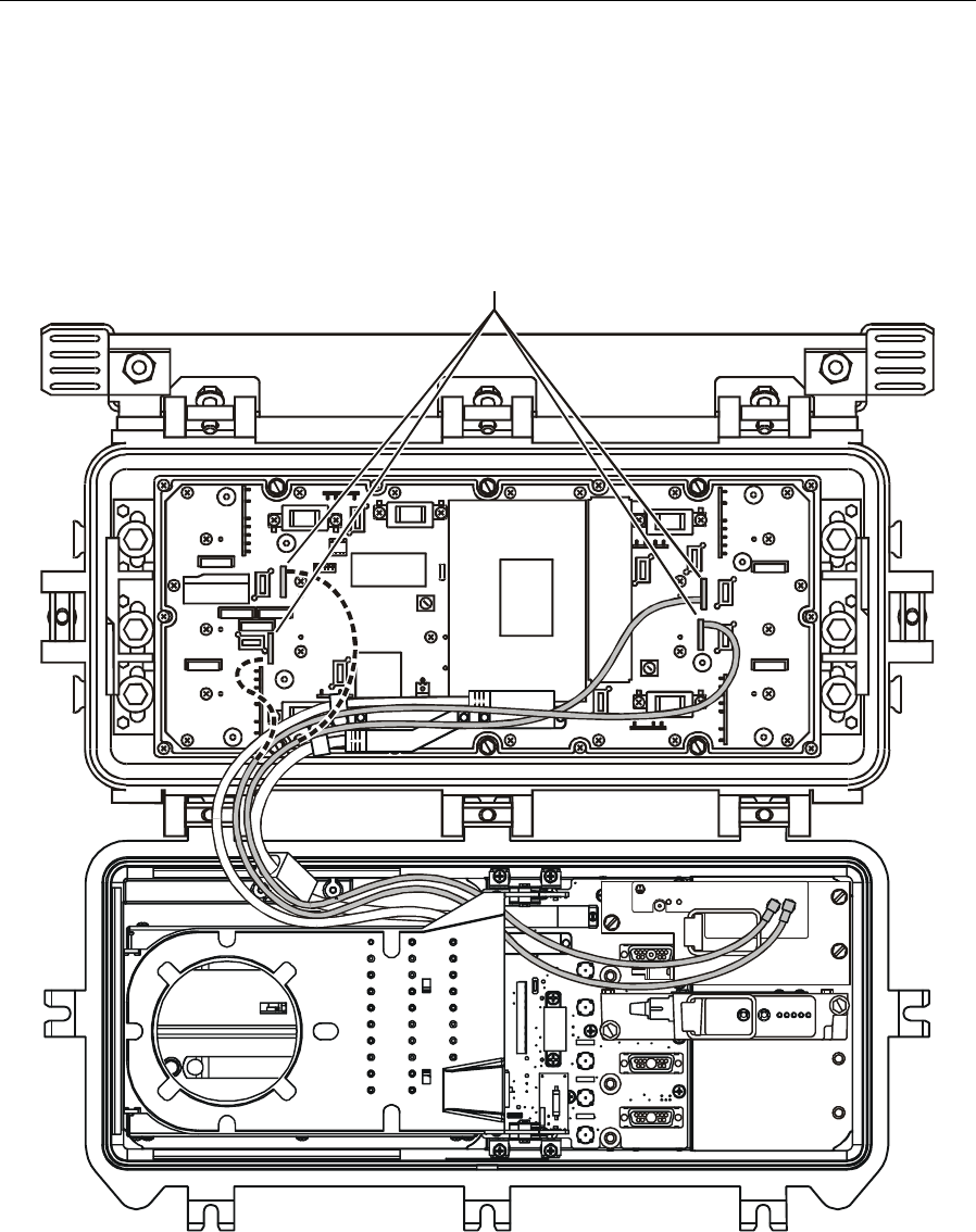
Figure 10 illustrates the SG2000 equipped with an SG2-RPM/C, the E-pack cover removed,
the ICS locations, proper cable routing and installed SG2-DRT-3X:
Figure 10
SG2-DRT-3X installed in SG2000
ICS connections
5 Install an SG2-DR-3X input board in each selected ICS location. The ICS locations on the
left are for ports 1 and 3 and the locations on the right are for ports 2 and 4.
6 Nest the attached cables between the components on the E-pack and toward the PIC cable
and status monitoring cable (optional).
7 Position the cover on the E-pack and route the cables through the bottom opening following
the PIC cable.