Premium Series H.264 DVR User’s Manual ▪ H.
Preface We welcome you as a new user of the world's best digital video recorder (DVR), and the leading Digital Video Surveillance System. For effective usage, please read this manual carefully. For future reference, please keep this manual close to hand. Copyright/Authentication/Trademark/Limited Warranty Copyright This manual is produced under copyright law. None of its contents may be copied or duplicated without prior approval.
Risk of death or serious injury. This is the highest priority danger warning. • RISK OF EXPLOSION IF BATTERY IS REPLACED BY INCORRECT TYPE. DISPOSE OF USED BATTERY ACCORDING TO THE INSTRCTIONS. • THIS EQUIPMENT IS INDOOR USE AND ALL THE COMMUNICATION WIRINGS ARE LIMITED TO INSIDE OF THE BUILDING. • Please connect the power cord only to the type of AC outlet indicated in the manual or product specification. If connected to other types of power outlet, fire and electric shock may result.
Risk of minor injury or damage. • If a foreign substance is stuck to the product, remove it using a soft cloth or tissue. Do not use chemical agents (thinner, solvent, etc.) to remove the substance. • Do not operate or store the product in the following places.
Contents Preface ............................................................................................... 1 Copyright/Authentication/Trademark/Limited Warranty ................................................ 1 Cautions ................................................................................................................... 1 Contents............................................................................................. 4 Chapter 1. Introduction ......................................
2-5-3. MENU > NETWORK > Notification ........................................................... 32 2-5-4. MENU > NETWORK > Transmission ......................................................... 32 2-6. EVENT ............................................................................................................. 33 2-6-1. MENU > EVENT > Sensor ....................................................................... 33 2-6-2. MENU > EVENT > Motion .........................................................
Chapter 1. Introduction 1. The System This product is the one that you are looking for quite long time. Eventually, The DVR which is high performance real time DVR based on H.264, you can enjoy the full benefit of latest compression H.264 and be free from headache because of stability of the DVR. This product can distinguish the recorded data clearly compare to MPEG4 due to the motion artifact and will find the tremendous difference.
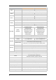
3. Specification Model 4 Channel Premium DVR In 4 BNC Out 1VGA,& 1 BNC Main, 1 Spot Output In 4 RCA (Line-In) Out 1 RCA (Line-Out) Sensor In 4 TTL Video Audio Device Display Alarm Out 2 Relay + 2 TTL I/O Interface RS232, RS485, USB2.0 x 1, USB1.1 x 1 for Mouse Speed Real Time Resolution 720 x 480 (NTSC), 720 x 576 (PAL) Split Screen 1, 4, PIP, Digital Zoom Compression H.
Model 8 Channel Premium DVR In Video Out In Audio Device Display 8 BNC 16 BNC 1VGA,& 1 BNC Main, 4 Spot Output 8 RCA (4 Mic in, 4 Line in) Out Sensor In Alarm Out 8 TTL 16 TTL 4 Relay + 4 TTL 4 Relay + 12 TTL I/O Interface RS232, RS485, USB2.0 x 3, USB1.
Chapter 2. System Installation 1.
2. Connecting Devices 2-1. 4 Channel Premium DVR The rear panel of the 4 channel premium DVR comprises the following: • Front USB: Two USB ports are provided to connect external devices like HDD, ODD, Flash memory for Backup, System upgrade or USB mouse on the front panel. A USB mouse can be connected only front panel USB port dedicated only for mouse. Video Input Connect the coaxial cables from the cameras to the BNC video connectors.
ETC • RS-232C: An RS-232C connector is provided to connect an ATM or POS machine for Text-In function. Use a cable with a DB9 (female) connector to connect to the DVR. • Network: Connect a Cat5 cable with an RJ-45 connector to the DVR connector for remote monitoring, remote playback, remote setup. See Chapter 3-2. DVR Configuration for configuring the Network connections. • Reset: The DVR has a Reset switch that will only be used to return all the settings to the original factory settings.
2-2. 8/16 Channel Premium DVR The rear panels of the 6/18 channel premium DVR comprise the following: [8 Channel Premium Model] [16 Channel Premium Model] Video Input Connect the coaxial cables from the cameras to the BNC video connectors. Loop-Through Video Connect the coaxial cables from the Loop BNC connector to another device. Audio Input The DVR can record audio up to 16(8) sources. Connect the audio sources to the Audio-In RCA connectors.
ETC • Audio Out: The DVR does not have amplified audio output, so you will need a speaker with and amplifier. • RS-232C: An RS-232C connector is provided to connect an ATM or POS machine for Text-In function. Use a cable with a DB9 (female) connector to connect to the DVR. • Network: Connect a Cat5 cable with an RJ-45 connector to the DVR connector for remote monitoring, remote playback, remote setup. See Chapter 3-2. DVR Configuration for configuring the Network connections.
3. Cautions • Avoid installing the product where there are direct rays or it is hot by locating near from heat generator. (May cause fire) • Do not put vase, flowerpot, cup, cosmetics, drug, and anything the contain water on product. (May cause fire or electric shock, and it may injure people by falling) • Do not insert or drop any metal object (coin, hair pin) or flammable object (match, paper) into air hole. (May cause fire or electric shock) • Do not put any heavy object on it.
Chapter 3. Using DVR 1. Basic Operation 1-1. Front Panel & IR Remote Controller The DVR should be correctly installed before proceeding. The location and the shape of the buttons may vary depending on the DVR model. (In 4-channel DVR, Only some of main buttons most commonly used can be found on the front panel.) Control Description Two USB ports are located on the front panel. A USB mouse USB Port can be connected USB port dedicated only for mouse as picture directed.
move down when setting the menu. - Zoom In under PTZ mode. EJECT Button PTZ Button ZOOM Button PIP Button It will open or close the backup drive such as CD-RW or DVD - Display menu to load PTZ presets under PTZ mode. Changes to the PTZ control mode from the live mode. Zooms the current image on the screen. Changes to PIP screen mode from live screen. FREEZE Button Freeze the current screen. AUDIO Button Selects a camera for live & playback audio output. SPOT Button Assigns the SPOT output channel.
Turns on when the system is connected to the network. Turns on when the Alarm is being activated. Archiving mode E.REC (Emergency Recording) Mode. Displays date & time. IR Remote Controller 1-4. Display Icons No Recording Recording (Red) E.
1-5. User or Admin Login Press MENU to enter main menu screen. Login in screen appears to enter ID (Administrator or User) and Password. Password can be set up to 8 numbers by the combination of numbers from 0 to 9. The factory default password is ‘none’ so press OK to log in to the system for a first time log in. Password can be set under password set up option (MENU > SYSTEM > User). System will be automatically log out if it is not in-use for sometime.
Address NETWORK DDNS Notification Transmission Sensor Motion EVENT Video Loss Text-In System LOGOUT SHUTDOWN 19
1-7. Contextual Menu Additional Contextual Menu screen appears by pressing right button on the Mouse. Layout option allows changing Camera on the monitor. Select preferred camera display option on the monitor. Camera : Select camera no. Layout : Select display mode (8/16 ch. DVR Only) OSD : Select OSD display option Text-In OSD: On/Off Text-In OSD.
2. DVR Configuration 2-1. SYSTEM Under SYSTEM menu, System configuration options for general Information, Date &Time, User, Quick Setup and System Log can be selected. 2-1-1.MENU>SYSTEM>Information In the Information screen, DVR Name, System Version, Upgrade, Mac Address and Configuration options can be selected. Highlight and press DVR Name to enter or change DVR name. Name the DVR by using the virtual keyboard. To Upgrade the system, save the upgrade file to USB Flash Memory and connect it to DVR.
2-1-2. MENU > SYSTEM > Date & Time In the Date & Time, Time Zone, Date, Time, NTP Server, Holiday options can be selected. Highlight and press Time Zone to select right Time Zone. Select ‘Use Daylight Saving Time’ if it is applicable. Enter start and end date/time for local ‘Daylight Saving Time’. Press button to set up Date and Time. Press Format button to select a date & time display format. Select ‘Use NTP’ to enter Time Servers to be synchronized with DVR.
User Name: Enter a user name Group: Select a Group which a new user will belong to Password: Set a new password or change a password. Note : DO NOT have to enter Current password when setting password for the first time as there is no default password for Admin/User. Set user registration and access rights for the system. Press Group tap to add and set group. Press to add a new group. Enter a group name and select access rights for a group. To remove an existing Group, press next to it. 2-1-4.
2-2. DEVICE Under Device menu, Device configuration options for Camera, Audio, Alarm, Keyboard and RS232 & RS485 (POS/PTZ) can be selected. 2-2-1. MENU > DEVICE > Camera Set Camera display option. Camera display (video loss display) can be disabled by unmarking the box next to it if there is no camera connected. Press to change Camera title. Press button under Type to select Monitoring option. Normal: Normal camera display Covert Low: No display of video image on screen but OSD still remains on screen.
Zoom Out Zoom In Focus on near distance Focus on far distance Save Presets Load Presets 2-2-2. MENU > DEVICE > Audio Select Audio for Audio recording. Gain Control Menu is available for Mic-In inputs only. (8/16 ch. DVR Only) Control Gain value using button. 2-2-3. MENU > DEVICE > Alarm Alarm duration: Set Alarm activation time from 5 seconds to 10 minutes. Select Schedule tap to schedule Alarm operation. Alarm can be set by day, time, mode and inputs (camera).
2-2-4. MENU > DEVICE > Keyboard Press to find and select keyboard from the list. 2-2-5. MENU > DEVICE > RS232 & RS485 Press to select a device for each ports. RS232: Supports Text In (POS) device. PTZ and Keyboard RS485: Supports Text In (POS) device ,PTZ and Keyboard. Note: Text In devices (e.g.
2-3. DISPLAY Under Display menu, Display configuration options for OSD and Monitor can be selected. 2-3-1. MENU > DISPLAY > Display Language: Select system language. Press to find available language options. Hide Status Bar: Select On/Off and time to hide Status Bar when system is not in use. OSD margin: Set OSD margin (position) using . Freeze: Display an image in either Field or Frame format when it is in still (freeze) mode. Layout: Allows to change or reallocate video inputs’ (cameras) displays.
2-3-2. MENU > DISPLAY > Monitoring Event Pop-up: Pops up the camera image in full screen when pre-set event occurs. Sequence Interval: Set time interval between cameras under sequence mode. Event Pop-up: Pops up the camera image in full screen on spot monitors when pre-set event occurs. Sequence Interval: Set time interval between cameras on spot monitors for sequencing. Select camera display option on spot monitors. Spot outs support full and sequential camera displays.
2-4-2. MENU > RECORD > Record In Record, general recording options can be selected including overwrite, resolution, speed, recording quality and etc. Overwrite: Select Overwrite to overwrite recorded HDD data when it is full. Audio Record: Select Audio Record to record audio with video image. Resolution: Select recording resolution.
Setting to set recording options. Use Default Setting: Check Use Default Setting to follow main recording setting under Record menu. 2-4-3. MENU > RECORD > Record Tools In Record Tools, estimated HDD usage and recording period can be calculated. Press Calculate once resolutions, ips, number of cameras and quality are set. The recording period is calculated based the size of HDD installed. The GB size shows the HDD size requires for a day recording.
2-5. NETWORK Under Network menu, Network configuration options for network Address, DDNS, Remote Notification and Transmission can be set up. 2-5-1. MENU > NETWORK > Address In Address, Information such as Type, IP address, Subnet Mask, Gateway Port and DNS can be set for network connections. Type: Select network type of Static or DHCP. button. ID Address: Enter IP address using Subnet Mask: Enter Subnet Mask using Gateway: Enter Gateway using button. button.
2-5-3. MENU > NETWORK > Notification In Callback, set up IP addresses of client sites so that Events detected in local system can be notified to multi remote client sites simultaneously. Enter IP addresses of client sites to receive events notifications on remote sites. Press to pop up the virtual keyboard. Callback Interval: Select Callback Interval to set time interval between consequential events being sent to remote site.
2-6. EVENT Under Event menu, events can be set in synchronization with Sensor, Motion, Video Loss, Text-In, System, 2-6-1. MENU > EVENT > Sensor In Sensor, each sensor can be selected for activation and its type. Select Sensor Type using button. NC: Normally Closed NO: Normally Opened In Record, each sensor can be synchronized with single and multi cameras. Press to select cameras to be synchronized with sensors. In Alarm, each sensor can be synchronized with single and multi alarms.
2-6-2. MENU > EVENT > Motion In Motion, system provides Motion Detection function. Set Motion Detection using Sensitivity, View and Area options. Sensitivity: Select motion sensitivity from Very Low to Very High. View: On or Off the appearance of motion zones on screen when motions is detected. Area: Define the area for motion detection. Press Setup under Area to define motions detection areas.
In Notification, each camera with motion can be synchronized with single and multi callback or emailing sites. Press to enter callback or email address to be synchronized with cameras for motion events. 2-6-3. MENU > EVENT > Video Loss In Video Loss, single or multi cameras can be synchronized for event recording when there is a video loss. Press to select single or multi cameras to be synchronized with cameras for video loss.
2-6-4. MENU > EVENT > Text-In The system allows Text In from POS/ATM machines. Note: For use of POS/ATM, the system must support general ASCI code. Text-In Model: Select Text-In model from the list Transaction Begin: Enter a word which the transaction info to be displayed on screen as a start. Any Character: Check Any Character to start display a text with any character as a start. Transaction End: Enter a word of last line where the transaction info to be displayed on screen as the end.
In Notification, text event can be synchronized with single and multi callback or emailing sites. Press to enter callback or email address to be synchronized with text event. 2-6-5. MENU > EVENT > System In System, S.M.A.R.T function monitors storage conditions such as Temperature, Conditions and Recording. S.M.A.R.T Threshold allows to pre set tolerable temperature level of storage.
3. Playback The system provides various playback menu to search recorded data. Please press right mouse button on mouse or press playback button on the front panel. 3-1. Go to Time Select Go to Time to search recorded data by time/date. Set time/date using button. Go to Beginning and End options are selectable to search the very first and last data recorded. Once desired settings are completed, press OK to begin playback. Go to Beginning : Move to the very first recorded data.
3-3. Event Search Event Search provides easy search by event list recorded. Select the date and type of event to find specific data. Press Event: All section on the tope of the list to display event search options.
3-5. Backup Data Playback Backup files on backup medias can be played on DVR. Insert the media with backup files and select a file to playback it on DVR. 3-6. Playback Control R.Play: Reverse Playback Step Backward: Go to the previous image Pause: Freeze or Stop current image Step Forward: Go to the next image Play: Play the data at normal speed To control the backward and forward playback speed, press on ◀ or ▶ repeatedly. Playback speed can increase up to x32.
4. Backup 4-1. Backup In the BACKUP, the recorded data can be selected for backup to USB devices. Press USB Device to select the type of USB Device connected to the system. Select date & time period of data to be backup using button. Select Camera number to be backup or All to backup all the data recorded during the selected period. To back up recorded Audio with video data together select Audio.
It may cause critical damage to either the media or system if the backup media is removed during the backup process." Note: Playback speed will be slower than usual while instant back up is processing. 4-3. Clip Maker Clip Maker allows to create single channel backup file which can be played on PC. Select Clip Maker option on the pop up menu during the live or pause mode on the playback. Select the backup option for Clip Maker. Press Start button to create Clip Maker.
Chapter 4. Remote Software NEMON 1. NEMON Installation Find Software CD contains ‘Nemon’ in the box and Insert CD into PC. Double click on NemonSetup.exe file to start installation procedure. When the following dialog box appears, click Next After selecting program folder and desired option, click Next • Everyone : Allow all PC users to get access to Nemon software. • Just me : Allow only private PC user access to Nemon sotfware.
When the following dialog box appears, click Click 44 Close Next to complete installation procedure.
2. Using NEMON 2-1. Starting the Software Double click on ‘Nemon’ icon on PC to run the software. Main screen of the remote software appears as shown below. Close Live Playback Display Mode The location of icons and buttons may vary depending on the product model or software versions.
2-2. Site Set Up Click Click button to display registered remote locations or add new locations. Add button to add remote location and required information.
Click OK to save information and complete the registration. Double click the location or Highlight it and click Connect button to get connected to the site. The DVR and Client program on PC start searching each other once they are on the same local network. The Auto Detect menu shows the DVRS detected on the same local network. Note: This function is only available on local networks. No settings are required if both DVR and PC use DHCP.
2-3. Favorite Set Up Favorite function allows multi site management. Up to 64 different cameras and sites can be monitored and managed on one screen. button and select Click Click Add Favorite tap. button to group multiple sties as one favorite group. Enter the group name and description. Up to 64 different cameras or sites can be grouped and displayed together.
2-4. Play Backup Data Backed up data from the local site can be played on the remote site. Select the location where the data is saved. Select the file and click Connect to play the video. Note: Recorded Audio can be played on single screen only. 2-5. Play Independent HDD Data on PC Independent HDD (removed from a DVR) data can be played on PC using Nemon S/W. Have the HDD connected to PC using a SATA to USB connector cable.
3. Remote Playback 3-1. Calendar Search • Click on • Click icon on the menu screen to bring up search menu. for Calendar search. Dates with recorded data will be displayed in bold letter. Select the date and use time table to select specific time. Click Play button to start playback. Playback Control Button Rewind Reverse Play Beginning Step Backward Stop Step Forward End Play Fast Forward Go To Time • Click on • Click on 50 icon to display time search window.
3-2. Event Search • Click tap to display menu for Event search • Click to enter event query option. Select an event from the list for playback. Search trough the list using buttons. Select the date of event search for from the Date list. Select All or specific camera numbers for related event search. Type of events can be selected from the list for detail and effective search. 3-3.
Save to AVI • Pause the playback and press button to save the recorded data in AVI file format. ‘Save AVI’ dialogue will appear. • Enter file name and select Location. • Select appropriate Codec. • Select the time period. • Select Camera number and Audio. Press Start to create AVI file. Save to Backup • Pause the playback and press button to backup the recorded data. ‘Backup’ dialogue will appear. • Enter file name and select Location. • Select the time period. • Select Camera number and Audio.
4. Setup 4-1. Nemon Setup Click on to enter local setup menu. Product Name: Displays general information of the S/W Software Version: Displays current S/W version Load: Load saved data for settings for remote software Save as: Save current settings of remote software Default: Set default settings of remote software Click on display tap to enter remote display setup menu.
Click on Callback tab to enter Callback setup menu. Please set network ports (8000~12000, default: 10110) for Callback function.
4-2. Remote Setup Click to enter remote set up menu. Single connection (single site): please get a site connected for monitoring first, and click Button. Favorite connection (multi sites): please click camera or site on the monitoring screen, and click button. Note: The remote software provides interactive setup system that allows easy local DVR settings from remote sites. It gets exactly same menu and options as the local system. Therefore please refer to “Chapter 3-2.
5. Nemon Callback Start-> Program -> Network Monitoring Software -> Nemon Callback Nemon Callback icon will be displayed on the bottom right of Window once the program starts. Callback message will be displayed/notified as shown above. Click Nemon Callback icon to display main window of Callback as shown below. Select a log from the list and click Live or Playback icon image to connect related DVR.
Clear: Clear all the logs listed on Nemon Callback window Log: Click Log button to display log search window as shown below. Up to 100,000 log can be saved. 1,000 log lists will be displayed per search. Click More button to display next 1,000 logs. Click Export button to save searched logs in either txt or csv format. Setup: Click Setup button to set a port for Callback.
Appendix A. Remote Access Using I.E. DVR can be accessed remotely using Internet Explore. Execute internet explore program and enter DVR address (e.g. IP) to get connected. Remote Log In page appears once connected to DVR. Enter ID, PW and Port information, and select Live or Playback mode to display desired remote control option. Please install Active X when Internet Explore displays Active X installation message.
COMPLIANCE NOTICE OF FCC: THIS EQUIPMENT HAS BEEN TESTED AND FOUND TO COMPLY WITH THE LIMITS FOR A CLASS A DIGITAL DEVICE, PURSUANT TO PART 15 OF THE FCC RULES. THESE LIMITS ARE DESIGNED TO PROVIDE REASONABLE PROTECTION AGAINST HARMFUL INTERFERENCE WHEN THE EQUIPMENT IS OPERATED IN A COMMERCIAL ENVIRONMENT. THIS EQUIPMENT GENERATES, USES, AND CAN RADIATE RADIO FREQUENCY ENERGY AND IF NOT INSTALLED AND USED IN ACCORDANCE WITH THE INSTRUCTION MANUAL, MAY CAUSE HARMFUL INTERFERENCE TO RADIO COMMUNICATIONS.