
User Manual

4400-46001.A.00 Tri-Reader 3 User Manual
This document contains proprietary and confidential information originated or owned by Cubic. Neither this document nor the
information disclosed herein shall be reproduced or transferred to other documents or used or disclosed to others for
manufacturing or any other purposes except as specifically authorized in writing by Cubic.
December 2, 200
8
3
2.3.1 RF Field Strength
The magnetic field strength is approximately 9 A/m in the center of the antenna and falls off by the third power
of the distance. The electric field strength is determined by the voltage applied to the coil as well as the
efficiency of the antenna as a radiator. The effective applied voltage is approximately 12 Vrms, but the
antenna is fitted with a balanced shield, reducing the apparent common mode voltage to 0.
2.3.2 Modulation Types
The signals for communication between the Tri-Reader 3 and the CSC will differ between card types. In some
cases, data will be modulated onto a carrier only, while in others a subcarrier will also be present. The
modulation schemes used for communication also differ from one card type to another as described below:
CSC Type A: Reader-to-card, ASK 100% modified miller, 106 kb, 212 kb and 424 kb.
Card-to-reader, ASK - Manchester, load modulation—subcarrier fc/16,
847.5 kHz, 106 kb, 212 kb and 424 kb.
CSC Type B: Reader-to-card, ASK 10% modulation index NRZ, 106 kb. Card-to-reader,
BPSK-NRZ load modulation subcarrier fc/16, 847.5 kHz, 106 kb.
Type GO CARD: Reader-to-card, ASK 8% modulation index NRZ, 115.2 kb. Card-to-reader,
ASK-NRZ load modulation, 115.2 kb.
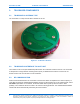
2.4 TRI-READER 3 PRINTED CIRCUIT BOARD SIZE
The Tri-Reader 3 consists of an 86.5 mm diameter circular digital board, an 82 mm diameter circular analog
controller board and an 83 mm diameter antenna board. Thickness, including components and antenna
board, is 17 mm, except for the RJ45 connector which extends 10 mm above the components on the back of
the board, giving a maximum thickness of 27 mm.
2.5 TRI-READER 3 PHYSICAL INTERFACES
The following physical interfaces apply to the Tri-Reader 3:
1. The Tri-Reader 3 is powered from 8 to 24 Vdc. It can draw a maximum current of 1.5A (at startup)
and dissipates up to 2.8 watts. This can be supplied either via an expansion connector (J8) or it can
be tapped from the host communication cable, in which case it will come in on the RJ45 serial
comms connector (see the pinouts below).
2. The Tri-Reader 3 comms can be set to be either RS-232 or RS-422/485 levels. RS-232 mode is
selected by software.
3. The Tri-Reader 3 has automatic baud rate detection between 9,600 bps and 921,600 bps.
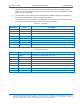
4. If RS-232 is used, only two of the four comms lines on the RJ45 connector are required. Pin 2 on
the RJ45 connector is the Tri-Reader 3 receive line (232Rx) and should be connected to the host
computer Tx output (pin 3 on a normal DB9). Pin 6 on the RJ45 connector is the Tri-Reader 3
transmit (232Tx) line and should be connected to the host computer Rx input (pin 2 on a normal
DB9).