
User's Manual
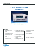

T-4180 HF DSP EXCITER HALF-RACK SPECIFICATION
FREQUENCY
Frequency Range: 1.6 to 30 MHz
Tuning Step Size: adjustable 1 Hz
to 10 MHz in decade steps
Synthesizer Tuning Speed: (from
receipt of last command byte until
within 1 kHz of the final fre-
quency): all modulation modes
∆f<100 kHz <1.0 msec, typical
∆f<1 MHz <1.5 msec, typical
∆f<10 MHz <2.0 msec, typical
Sweep and Scan Speed:
100 channels per second
Tuning Accuracy:
Internal Standard TXCO: ±1 ppm
of tuned frequency
External Standard: equal to
accuracy of external standard
in ppm
Internal/External Frequency
Standard: 10 MHz
MODULATION
Modulation: LSB, USB, ISB, AM,
FM, CW, FSK, FMfax, LSBfc,
LSBpc, USBfc and USBpc
Bandwidth may be automatically
selected by modulation mode and
modulation characteristic
LSB, USB, 2-channel ISB and
CW per MIL-STD-188-141A,
Table I and Paragraph 5.2.7.1
plus Figure 5
AM - 6 kHz default or as selected.
Amplitude Modulation up to 95%
FM bandwidth automatically
selected for specified modula-
tion characteristics. Deviation up
to 5 kHz
Internal Modulation: 50 Hz -
6 kHz sine wave or white noise
Emission Designators supported:
A1A/A1B, A2A/A2B, A3E, B8E,
F1A/F1B, F1C, F3E, H2A/H2B,
H3E, J2A/J2B, J3E, R2A/R2B, &
R3C/R3E
RF SECTION
Exciter Power Output: +27 dBm
maximum
Output Impedance: 50 ohms
Output VSWR: 2:1 maximum
RF On/Off Switching Speed:
<80 µsec, 60 dB isolation,
controlled by external TTL levels
RF Filters: eight suboctave
bandpass filters reduce harmonic
content
Automatic Level Control (RF):
0 to -60 dB level control from
single RS-422 (dedicated from PA
microcontroller)
Manual Level Control (MLC):
-33 to +27 dBm in 1 dB steps
Phase Noise: Per MIL-STD-188-
141A, Paragraph 5.2.5 and Figure
3 fixed site, non-cosited
Phase Stability: Exceeds
MIL-STD-188-141A, Para-
graph 5.2.4
Absolute Delay: 5 ms maximum
Keying Characteristics:
Attack Time Delay: 3 ms max to 90
percent of full steady state output
Release Time Delay: 3 ms max to
10 percent of full steady state
output
Keying Time: Defined as time from
“key down” to RF output or “key
up” to reduce RF output
NOISE AND DISTORTION
In-band Noise: -105 dBc/Hz
In-band Intermodulation Distortion
(IMD): 50 dB below either tone of
two equal signals producing
+21 dBm PEP
Spurious Broadband Emissions:
per MIL-STD-188-141A, Para-
graph 5.3.2.1 and Table II
Harmonic Outputs: -55 dBc. All other
discrete spurious are -80 dBc
Carrier Suppression: -60 dBc for a
single tone at +27 dBm signal
output
Unwanted sideband suppression: -60dB
IF SECTION
1
st
IF: 24 kHz, DSP generated,
lowpass filter @ 80 kHz
2
nd
IF: 456 kHz, Standard Filter BW
is 18 kHz
3
rd
IF: 40.456 MHz, Standard Filter
BW = 22.5 kHz
IF Filters: 51 DSP derived FIR filters
provide bandwidths from 100 Hz to
16 kHz automatically chosen by
modulation mode and modulation
characteristics
INPUT CHARACTERISTICS
Unbalanced Audio Input
Impedance: 150 ohms ±10% over
100 to 7000 Hz passband
Audio Input Level: -45 to -15 dBm
ref. 150 ohms
Balanced Audio Input Impedance:
600 ohms, 0 dBm -20 dB to +10 dB
Audio Level Control: automatic
audio level control holds PEP
audio at standard level ±1 dB over
the 30 dB input range
REMOTE CONTROL
RS-232 and RS-422 available. All
exciter operational parameters
including SELCAL are remotely
controllable
BITE
Fault isolation to the module level
RELIABILITY
MTBF: 15,000 hours. Calculated
based on “Naval Sheltered” (NS) as
defined in MIL-HKBK-217F
MAINTAINABILITY
Mean-Time-to-Repair (MTTR) of not
more than 30 minutes at the module
replacement level
POWER REQUIREMENTS
90 - 260 VAC, 47 - 440 Hz, 60 watts
max., switching mode power supply
CONTROLS AND CONNECTORS
Front Panel:
Full alphanumeric display with full
function keypad for entry of all
parameters
Control knob for selection of all
numeric parameters
Power Switch: toggle-type:
Phone jack: 1/4 inch for micro-
phone and/or key line input
Rear Panel:
Power Connector: IEC
RF Output: BNC
External Frequency Standard
Input: BNC
Audio Input: 15-pin Sub D
PA Control: 15-pin Sub D
Bus Control: 25-pin Sub D for
RS-232 and RS-422