Professional Shop Manual Commercial Z-Wing NOTE: These materials are for use by trained technicians who are experienced in the service and repair of outdoor power equipment of the kind described in this publication, and are not intended for use by untrained or inexperienced individuals. These materials are intended to provide supplemental information to assist the trained technician. Untrained or inexperienced individuals should seek the assistance of an experienced and trained professional.
TABLE OF CONTENTS Introduction ........................................................................................................................................... 1 Spindles and Blades ............................................................................................................................. 1 PTO Belt ................................................................................................................................................ 3 Deck Belt .........................
2
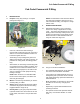
Cub Cadet Commercial Z-Wing Cub Cadet Commercial Z-Wing 1. INTRODUCTION 1.1. Purpose: Heavy-duty mowing in a compact package. See Figure 1.1. NOTE: The information in this manual is derived from prototype equipment. Although it is accurate at the time of writing, it is subject to change without notice. 2. SPINDLES AND BLADES 2.1. Flail blades have been in use on “bat-wing” mowers in a variety of applications for many years.
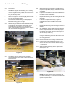
Cub Cadet Commercial Z-Wing 2.3. Precautions: • Disable the engine while working on the cutting deck: Disconnect the sparkplug leads, disconnect the negative battery cable, and remove the key from the key switch. 2.6. When performing any blade or spindle service, inspect the spindles, pulleys, and belts for wear or damage. 2.7. Inspect the hardware that secures the blades to the blade mount assemblies. • Allow the engine to cool thoroughly before working near the exhaust system.
Cub Cadet Commercial Z-Wing 2.13. The blade assemblies may be sharpened and balanced similar to conventional blades, but a straight-edge should be used to confirm that the blades are straight out. If the blades are partially folded during balance checking, the results will be thrown-off. 3.4. Remove the belt covers that protect the blade spindles using a 9/16” wrench. 3.5.
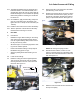
Cub Cadet Commercial Z-Wing 3.8. A second 1 1/8” wrench may be applied to the top of the nearest blade spindle if more rotation is needed. See Figure 3.8. Stack pulley 4. DECK BELT 4.1. Remove the PTO belt as described in the PTO Belt section of this manual, including all precautions. 4.2. Remove both deck belt covers using a 9/16” wrench. 4.3. Working from the right of the mower, use a 1/2” breaker bar to move the deck belt tensioner pulley arm, relieving tension from the deck belt. See Figure 4.
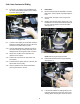
Cub Cadet Commercial Z-Wing 4.6. Check the blade spindles for looseness while the belt is off. 4.7. Reverse the removal process to install a new belt or belts. 4.8. Test the operation of the mower and its safety features before returning the mower to service. 5.5. Withdraw the spindle bolt and washers, and remove the pulley. See Figure 5.5. Thick hub boss faces up on all spindle pulleys Heavy washer Flat washer Figure 5.5 5. SPINDLE SERVICE 5.1.
Cub Cadet Commercial Z-Wing 5.8. The steel shields are identical top and bottom, and are easily removable. They do have barbed lips that may damage the seal when removed. they should not be removed unless the seals are to be replaced. See Figure 5.8. 5.10. If the tapered roller bearings need to be replaced, the races need to be driven-out and replaced as well. See Figure 5.10. Race (upper spindle bearing) Spindle housing Seal Lip Sealing surface Steel shield Figure 5.10 Figure 5.8 5.9. 5.11.
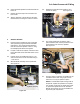
Cub Cadet Commercial Z-Wing 6. DECK BELT AND PTO BELT TENSIONER 6.5. 6.1. The deck belt tensioner idler arm can be removed using a 1” wrench on the bolt head above the deck and an 11/16” wrench to remove the nut, lock washer, and flat washer from beneath the deck. See Figure 6.1. The pulley is mounted to the idler arm using a carriage bolt. It can be easily removed using a 9/ 16” wrench. 6.6.
Cub Cadet Commercial Z-Wing 6.10. There are three mounting holes for the pulley on the idler arm, use the one nearest the pivot point as indicated by the “48” mark on the label. See Figure 6.10. 7. CUTTING DECK REMOVAL: EARLY 2005 PRODUCTION NOTE: Decks having U-shaped front lift rods were used on all Z-Wings produced after Nov. 1, 2005 (S/N: 0K015Z00001). These decks are retrofitted to earlier production.
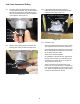
Cub Cadet Commercial Z-Wing 7.3. Remove the wing lift shield using a 9/16” wrench. See Figure 7.3. 7.5. Block all four hinge locks into the unlatched position using extra wrenches. See Figure 7.5. Wing lift shield Hinge lock Figure 7.3 7.4. Figure 7.5 Mowers produced after mid-season 2005 (2005/ 2) are equipped with a lateral brace between the frame and the mowing deck, similar to a panhard rod in the rear suspension of a car or truck.
Cub Cadet Commercial Z-Wing 7.9. Disconnect the wires from the deck wing position switches on each rear deck wing bracket. See Figure 7.9. Rear deck wing hinge • Hold the lift handle down • Carefully remove the hairpin clip and clevis pin that kept the lift handle in the lowest position. • Carefully allow the lift handle to rise to the transport position under the force of the lift assist springs. • Turn the front caster wheels sideways for deck clearance. 7.15.
Cub Cadet Commercial Z-Wing 8. CUTTING DECK REMOVAL: COMMENCING WITH LATE 2005 PRODUCTION 8.3. Remove the wing lift shield using a 9/16” wrench. See Figure 8.3. NOTE: Decks having U-shaped front lift rods were used on all Z-Wings produced after Nov. 1, 2005 (S/N: 0K015Z00001). These decks are retrofittable to earlier production. Earlier decks are easily identified by V-shaped front lift rods that connect to the deck at a single point. 8.1.
Cub Cadet Commercial Z-Wing 8.6. With the wings unlatched, they can be lifted manually. Lift the wings manually to put slack in the lift cable so that the end of the cable can be slipped-out of the hole and slot in the bracket. See Figure 8.6. 8.10. Release the extension spring that maintains tension on the PTO belt tension arm and pulley. Use a length of starter rope or a spring removal tool. See Figure 8.10.
Cub Cadet Commercial Z-Wing 8.12. Move the deck forward to disengage the front deck lift bar from the hooks on the front of the deck. See Figure 8.12. 8.16. Installation is done by reversing the removal process. Installation notes: • Confirm the correct operation of all safety features, including the wing-latch mechanisms before returning the mower to service. • Confirm that the cables ar correctly adjusted after deck installation.
Cub Cadet Commercial Z-Wing 9.2. Side-to-side measurement: See Figure 9.2. 9.4. Side-to-side leveling: See Figure 9.4. Adjustable link: left-hand side Figure 9.2 • Orient the outer pair of blades fore-and-aft. • Check the vertical play on each element of the blade assemblies to be measured. There will be some up and down travel at the blade tips, generally between 1/8” and 1/4” (3.175mm and 6.35mm).
Cub Cadet Commercial Z-Wing 9.6. Deck pitch adjustment: Mowers produced before November 2005. See Figure 9.6. Adjustment bolt Spherical rod end • Loosen the jam nuts that lock against the front rod lift tube using a 15/16” wrench. • Tighten or loosen the pitch adjustment nuts as required to achieve a nose-down blade attitude (lower at the front of the blade than at the back) of 1/8” to 1/4” (3.175mm and 6.35mm) using a 15/16” wrench. • Tension on the adjusting nuts should be even.
Cub Cadet Commercial Z-Wing 9.11. To adjust the lateral brace: See Figure 9.11. 10. DECK WING AND HINGE LOCK NOTE: Mowers produced after mid-season 2005 use a different hinge lock mechanism than the early 2005 production mowers. While the two hinge locks are similar in operation, the actual components differ substantially. The revised hinge locks will be described in a sub-section that follows the early hinge lock section. Mounting nuts / bolts Spherical rod ends 10.1. How it works: See Figure 10.1.
Cub Cadet Commercial Z-Wing 10.4. The lift mechanism can be reached by removing the lift wing shield using a 9/16” wrench. See Figure 10.4. NOTE: All four sets of hinge locks and brackets are identical: the parts are interchangeable leftto-right and front-to-rear. 10.3. When the wing lift is activated, all four cables, hinge locks, and lift mechanisms should work in unison: See Figure 10.3. Cable bracket Hinge lock Socket-head cap screw Lift wing shield Figure 10.
Cub Cadet Commercial Z-Wing 10.6. Orientation: on all four cable brackets, one side of the bushing shoulder is thicker than the other. The socket head cap screw always goes on the side with the thicker shoulder. See Figure 10.6. Cable bracket 10.10. Once the spring is released, remove the nut from the carriage bolt that secures the hinge lock and its shouldered bushing to the bracket on the deck wing. See Figure 10.10.
Cub Cadet Commercial Z-Wing 10.12. Assembly notes: See Figure 10.12. 10.14. The switch contacts are normally open (N.O.), meaning that the internal contacts are broken when the plunger is extended. See Figure 10.14. 1” Plunger down Contacts closed Figure 10.12 • Reverse the disassembly process to install the hinge lock. • Lubricate the pivot point (shoulder bushing) with anti-seize compound. • Tighten the nut on the carriage bolt to a torque of 20-25 ft-lbs (27-34 Nm).
Cub Cadet Commercial Z-Wing 11. HINGE LOCK: LATE 2005 PRODUCTION 11.1. When the wing lift is activated, all four cables, hinge locks, and lift mechanisms should work in unison: See Figure 11.1. • There is a torsion spring connecting the hinge to the cable bracket, giving the cable bracket more positive return action. • A J-nut has been positioned in a notch on the hinge. The J-nut is hardened. This provides a hard flat surface for the hinge lock to operate against.
Cub Cadet Commercial Z-Wing 11.4. The lift mechanism can be reached by removing the lift wing shield using a 9/16” wrench. See Figure 11.4. 11.6. The cable bracket can then be removed using two 9/16” wrenches. Unbolt it and remove the bushing. See Figure 11.6. Cable Cable bracket Bushing Lift wing shield Figure 11.4 Figure 11.6 11.5.
Cub Cadet Commercial Z-Wing 11.9. Assembly notes: See Figure 11.9. 11.10. To remove the hinge lock, the compression spring that holds the hinge lock against the bracket on the deck wing must first be disconnected. See Figure 11.10. Spring Flat washers Nut Figure 11.9 • • Reverse the disassembly process to install the cable bracket: hook the long arm of the torsion spring under the machine screw on the deck wing hinge, and position the socket head cap screw under the hinge lock. Figure 11.10 11.11.
Cub Cadet Commercial Z-Wing 11.13. The hinge lock and the bushing that it pivots on can then be removed from the deck using a 9/ 16” wrench. See Figure 11.13. 11.16. The switch contacts are normally open (N.O.), meaning that the internal contacts are broken when the plunger is extended. See Figure 11.16. Contacts closed Carriage bolt Hinge lock latched Plunger down Hinge lock Bushing Figure 11.16 Figure 11.13 NOTE: The cable bracket must be removed to release the carriage bolt. 11.14.
Cub Cadet Commercial Z-Wing 11.18. The switches are correctly adjusted when the contacts break just as the corner of the hinge lock clears the corner of the hinge. See Figure 11.18. 12.4. To remove the wing lift actuator, remove the cutting deck as described in the CUTTING DECK REMOVAL section of this manual. 12.5. Retract the actuator: Corner of hinge • Insert the key in the key switch and turn it to ON.
Cub Cadet Commercial Z-Wing 12.8. Disconnect the front of the actuator: • Remove the hairpin clip from the clevis pin that secures the front of the actuator to the frame of the mower. • Hold the actuator to keep it from rotating. • Drive the clevis pin up, releasing the actuator. Installation notes, continued: • Lubricate the pivot points (clevis pins) with antiseize compound.
Cub Cadet Commercial Z-Wing 12.16. If the nuts are loosened from their carriage bolts in small increments and slight downward force is applied to the bracket, the square bosses on the carriage bolts will remain engaged to the frame. Tape placed over the heads of the carriage bolts will also help keep them in place. See Figure 12.16. 12.19. Disconnect the front of the actuator: See Figure 12.19. Removing clevis pin Figure 12.19 Tape to temporarily secure carriage bolts Figure 12.16 12.17.
Cub Cadet Commercial Z-Wing 12.23. With the jam nuts removed, the threaded end of the cable housings will pass through the keyhole shaped slots in the end to the cable bracket. 12.26. While the cable bracket and actuator mounting bracket are disassembled, inspect the rollers and their mounting hardware. See Figure 12.26. 12.24. With the cables free of the cable bracket, the actuator mounting bracket can be rolled out the end of the cable bracket. See Figure 12.24.
Cub Cadet Commercial Z-Wing 12.28. On the early design, the rollers of the actuator mounting bracket rode in a channel formed by the bottom lip of the cable mounting bracket, supporting the lift actuator. 12.31. Installation notes: See Figure 12.31. Ground flat 12.29. The rollers on actuator mounting brackets made since November of 2005 only contact the top surface of the cable mounting bracket. See Figure 12.29. Index mark Rollers not enclosed in channel Figure 12.
Cub Cadet Commercial Z-Wing 13. DECK WING LIFT CABLE ADJUSTMENT NOTE: The bat wing feature of the Z-Wing mower is a key element in the sales of the mower. Safe and dependable operation of the feature is crucial to customer satisfaction. Correct adjustment of the cables is vitally important to the safe and dependable operation of the bat wing feature. NOTE: Whether the tightest cable is on the left or right wing, front or rear hinge, does not matter.
Cub Cadet Commercial Z-Wing 13.7. Operate the wings through 20 complete raise/ lower cycles: • Confirm smooth and consistent operation of the deck wings. • Confirm that all four hinge locks are locking and unlocking in sync. Jerky operation of 1 wing may indicate that 1 lock is unlocking later than the others. • Confirm that both deck wings are operating in sync. • Confirm that all four cables are secured in such a way that they will not be damaged by normal belt or linkage movement.
Cub Cadet Commercial Z-Wing 14.4. The deck lift arms and their connection points to the deck were modified in November of 2005. The new arms feature a bushing at the connection point to the cutting deck. See Figure 14.4. 14.7. Disconnect and remove each lift arm and lift link assembly. See Figure 14.7. T-head Lift arm Lift link Bushings Figure 14.7 Figure 14.4 14.8. Confirm that the deck height control is in the highest (Transport Lock) position, minimizing tension on the lift-assist springs.
Cub Cadet Commercial Z-Wing 14.9. Remove the locking nuts from each bolt that connects the lift assist springs to the bellcranks on the lift shaft assembly using a 9/16” wrench. 14.12. The bolts that hold the lift hub assemblies to the control housing are accessible through openings in the sides of the housing. See Figure 14.12. 14.10. Disconnect the springs from the bolts using a length of recoil rope or an appropriate hook tool. See Figure 14.10.
Cub Cadet Commercial Z-Wing 14.15. Rotate the left end of the lift shaft rearward to free the deck height control handle from the index assembly, and remove the assembly to a workbench. See Figure 14.15. 14.17. The left side hub will simply slip off of the shaft. See Figure 14.17. T-head for lift link Carriage bolt Lift shaft assembly Left lift hub Bungee cord Figure 14.17 Figure 14.15 14.18. The right side hub will slip off of the shaft as well, but it also retains the deck height control lever.
Cub Cadet Commercial Z-Wing 14.19. Assembly notes: See Figure 14.19. 15. LAP BARS 15.1. The lap bars do not have room to pivot outward in the conventional manner because they would interfere with the deck wings in the raised position. For this reason, separate pivot handles articulate on the lap bar pivot brackets which fasten to the steering pivot plate. See Figure 15.1. Pivot handle Figure 14.
Cub Cadet Commercial Z-Wing 15.3. The lap bar pivot brackets are adjustable to suit individual operators. See Figure 15.3. 16. CAUTION: Releasing the parking brake with the engine at top no-load speed and loose or misadjusted control linkages can result in unpredictable or uncontrolled movement of the mower.
Cub Cadet Commercial Z-Wing 17. LINKAGE NEUTRAL ADJUSTMENT 17.5. If the bolt that makes the connection between the steering link rod and the steering pivot plate is against the end of the slot in the plate, then the steering link rod will need adjustment. 17.1. Preliminary steps: • • Repair or replace any worn or damaged linkage components before attempting to adjust the steering linkage. 17.6. To reach the steering link rod adjustment point, remove the hydro service plate: See Figure 17.6.
Cub Cadet Commercial Z-Wing 17.8. Loosen the bolt that joins the steering link rod to the steering pivot plate using two 1/2” wrenches. 18. HYDRO NEUTRAL ADJUSTMENT NOTE: The neutral adjustment on the hydro is very rarely found to be out of adjustment. 17.9. Engage the parking brake, locking the steering pivot plate into the neutral position. 18.1. Before proceeding with the adjustment make a careful inspection of the return-to-neutral mechanism on the hydro pump. See Figure 18.1. 17.10.
Cub Cadet Commercial Z-Wing 18.3. The adjustment point is easily accessible through an oval-shaped opening near the rear of the control housing. See Figure 18.3. 18.13. Connect the steering link rods and repeat the adjustment described in the LINKAGE NEUTRAL ADJUSTMENT, which will have shifted slightly. 1/4” Allen wrench 18.14. Disconnect the negative battery cable. 18.15. Install the hydro service plate. 18.16. Reconnect the battery. 18.17.
Cub Cadet Commercial Z-Wing 19.3. Make an initial adjustment of the travel stops on each steering pivot plate: • • Push the lap bar forward gently to the limit of its travel as set by the hydro control linkage. Push the forward travel stop down against the top of the control housing, and tighten the nut that secures that stop. • Mark the position of the stops with a paint marker or magic marker; any further adjustment will be in the downward direction from these marks.
Cub Cadet Commercial Z-Wing 20. STEERING PIVOT SHAFTS AND BUSHINGS 20.6. There are two hex flange bushings supporting each steering pivot shaft. The outer-most can simply be pried out of the control housing. See Figure 20.6. 20.1. If the hex flange bushings that support the steering pivot plates become worn enough to effect the precision of the steering, they are easily replaced. 20.2. Set the parking brake. 20.3.
Cub Cadet Commercial Z-Wing 20.8. The steering pivot shaft.... See Figure 20.8. E-clip flat washer 21. 21.1. Description: The brakes are cam-actuated shoe brakes: Inner hex flange bushing Flats for wrench • Because they are cam actuated, if they are misadjusted in either direction, the brakes may drag, or fail to hold the mower with sufficient force. • The brakes are generously sized.
Cub Cadet Commercial Z-Wing 21.4. Characteristics of brakes that are too tight, continued: • 21.7. Each brake adjustment nut can be reached through an opening between the hydro service plate and the control housing. See Figure 21.7. High effort required to pull up the lever that applies the parking brake. Some “phantom” resistance may be created by the over-center action of the interlock linkage. 21.5.
Cub Cadet Commercial Z-Wing 21.9. Park the mower on a flat, firm, level surface, the engine turned-off, and the hydro relief valves open. 21.16. If the wheel does rotate, tighten the adjusting nut in half-turn increments until the wheel is held firmly. NOTE: If the mower has been run recently allow the engine and drive system to cool long enough to avoid burn injuries before beginning adjustment. 21.17. Release the parking brake, and confirm that it does not drag. 21.18.
Cub Cadet Commercial Z-Wing 21.23. Remove the hairpin clip that secures the brake rod to the brake arm. The brake return springs will center the brake arm. See Figure 21.23. 21.26. Carefully pry-off the clip that holds the brake arm onto the splined end of the brake cam shaft. See Figure 21.26. Brake arm, to be adjusted Spring clip Brake arm Figure 21.23 Figure 21.26 21.24.
Cub Cadet Commercial Z-Wing 21.31. The interlock is actuated by two steering lock rods; one for each steering pivot plate. The steering lock rods extend forward from the output arms on each end of the brake pivot shaft. See Figure 21.31. 21.34. The post is easily loosened for adjustment, or removal using a pair of 1/2” wrenches. See Figure 21.34. Brake output arm Steering lock rod Nut Steering lock rod Figure 21.34 Figure 21.31 21.35. A sleeve within a sleeve creates a shoulder bushing.
Cub Cadet Commercial Z-Wing 21.36. The steering lock post is installed on the control housing as illustrated below. See Figure 21.36. 21.38. When the linkage is in this fully extended position, push the post being adjusted as far as it will go in the notch in the rear edge of the steering pivot plate and tighten the nut. See Figure 21.38. Position handle here Plastic washer Slide post into notch Steel washer Large sleeve Small sleeve Figure 21.36 Figure 21.38 21.37.
Cub Cadet Commercial Z-Wing 22.6. Disconnect the bottom ends of the brake rods from the arms on the brakes by removing the hairpin clips. See Figure 22.6. 22.10. From this point, the brake pivot shaft can be driven far enough to achieve any necessary repairs using a soft drift. See Figure 22.10. Brake pivot shaft Output arm Hex flange bushing Brake rod Arm Figure 22.6 Figure 22.
Cub Cadet Commercial Z-Wing 22.12. Installation notes: • • • 23. Apply lubricant to the friction surfaces of the steering pivot shaft on assembly: In regions where the mower will be in continuous duty, a dry PTFE-based lubricant such as “Tri-flow dry Teflon Lubricant” is appropriate. This will lubricate the pivot shaft without collecting abrasive grit. In regions where there is an extended dormant period anti-seize compound will help keep rust off the bearing surfaces during times of disuse.
Cub Cadet Commercial Z-Wing 23.2. The hydraulic reservoir is accessible by tippingup the seat. See Figure 23.2. • The hose connected to the shorter tube at the front of the tank is the return line. • The hose connected to the longer tube at the rear of the tank is the pick-up line, feeding the hydrostatic pumps via the filter. 23.4. The hydraulic filter is mounted beneath a bracket just in front of the reservoir. It is accessible for service from below the frame. See Figure 23.4. Figure 23.
Cub Cadet Commercial Z-Wing 23.8. The fluid will also drain out of the lines leading to the pumps. See Figure 23.8. 23.10. The wheel motors are manufactured by White Hydraulics. There is no financial nor managerial relationship between White Hydraulics and White Outdoor Power. They are a separate company, and Cub Cadet Commercial is simply a customer. See Figure 23.10.
Cub Cadet Commercial Z-Wing 24.3. If the performance of the right side drive system is suspect, pay particular attention to the belt and tensioner. There is more belt wrap on the left pump pulley than the right because the tensioner is on the left side of the frame. See Figure 24.3. 24.6. Remove the wheels using a 3/4” wrench. See Figure 24.6. Belt Tensioner spring Tensioner pulley Pulley, left side hydro. pump Figure 24.6 24.4. Observe normal hydraulic precautions: 24.7.
Cub Cadet Commercial Z-Wing 24.9. Place a catch pan beneath the wheel motor connection to be removed, and loosen the hydraulic hose using a 1” wrench and a 7/8” wrench. See Figure 24.9. 24.15. Inspect the fluid for debris. Metal debris may indicate that the wheel motor is worn. This debris may enter the pump that is connected to the motor, causing accelerated wear on the pump. “B” port • If the wheel motor is going bad, the pump may be a victim part.
Cub Cadet Commercial Z-Wing 24.20. Match-mark, then loosen the roller used to make high-speed tracking adjustments using a 9/16” wrench. Lift it up to allow full forward motion, then snug-down the jam nut that locks the adjustment. See Figure 24.20. 24.22. Begin the flow droop test with the throttle set to 3,400 RPM: See Figure 24.22. 35 LPM Pressure: zero Valve: open Match marks Figure 24.22 Figure 24.20 24.21. Start the engine, release the brake, and work the drive system: See Figure 24.21.
Cub Cadet Commercial Z-Wing 24.23. After the 300 PSI (20.68 Bar) flow reading is noted, close the load valve further, until the pressure gauge reaches 1,100 PSI (57.85 Bar). Note the flow rate. See Figure 24.23. Flow: 26-27 LPM 25. 25.1. The drive system employs a pair of Hydro-Gear pumps: Pressure: 1,100 PSI Valve: nearly closed • If a hydrostatic pump suffers a warrantable failure, it is to be replaced as a complete unit.
Cub Cadet Commercial Z-Wing 25.4. Remove the nut and flat washer that secure the pulley to the input shaft that extends out the bottom of the pump using a 9/16” wrench. See Figure 25.4. 25.8. Remove the nut that secures the cooling fan using a 9/16” wrench. See Figure 25.8. Pulley Flat washer Nut Nut Cooling fan Figure 25.8 Figure 25.4 25.9. Lift-off the hub that the cooling fan rides on. 25.10.
Cub Cadet Commercial Z-Wing 25.13. Loosen the jam nut that secures the T-fitting to the “S” port on the right side hydro. pump or the L-fitting to the “S” port on the left side hydro. pump, depending on which pump is to be removed. Wrench size: 11/16”. 25.18. Remove the nuts that secure the pump to the frame using a 9/16” wrench. See Figure 25.18. Carriage bolts (nuts above frame) NOTE: This will allow the fitting to be rotated for better wrench access. 25.14.
Cub Cadet Commercial Z-Wing 25.21. If there is a possibility of fluid contamination, either as a cause of or a result of the pump (or motor) failure: • Replace the filter. • Drain and properly dispose-of the remainder of the fluid in the system. • Remove and clean or replace the hoses connected to the “A” and “B” ports of the pump. • Follow break-in procedure; initial fluid change after 50 hrs. of operation. 25.25. Prime the “S” hoses that lead from the filter, if they have lost substantial fluid.
Cub Cadet Commercial Z-Wing 25.30. Re-connect the negative battery cable to the negative terminal of the battery. 26. 25.31. Confirm that no hazardous conditions will be created by running the engine or operating the drive system. 26.1. The wheel motors used in this application are sourced from a company called White Hydraulics. 25.32. Open the relief valve of the newly installed pump. • Service parts are not available through Cub Cadet. 25.33.
Cub Cadet Commercial Z-Wing 26.4. Remove the wheel from the wheel motor to be replaced using a 3/4” wrench. See Figure 26.4. 26.8. Unbolt the wheel motor from the frame using a 3/ 8” allen wrench and a 3/4” wrench, and carefully remove it. See Figure 26.8. Allen wrench Figure 26.4 Figure 26.8 26.5. Release the parking brake. 26.9. On the bench: 26.6. Disconnect the brake rod from the brake arm. 26.7. Match mark and disconnect the hydraulic hoses from the wheel motor using a 7/8” wrench and a 1” wrench.
Cub Cadet Commercial Z-Wing 26.11. Reverse the removal process to install the wheel motor. See Figure 26.11. 26.13. Re-fill the reservoir with Hydraulic Drive System Fluid Plus. 26.14. Confirm that no hazardous condition will be created by running the engine or operating the drive system. Wheel motor removed 26.15. Open the relief valve of the pump that drives the newly replaced wheel motor. 26.16.
Cub Cadet Commercial Z-Wing 27. FRONT AXLE AND CASTER WHEELS 27.3. The front wheels can be removed from the yokes using a pair of 3/4” wrenches. See Figure 27.3. 27.1. The front wheels mount to the front caster yokes. See Figure 27.1. Zerk Bearing cap Valve stem Spacer tube Figure 27.3 Figure 27.1 • • • The wheels, bearings and tires are replaced as a complete assembly when they are worn or damaged. The tires may be plugged or sealed in accordance with the instructions in the operator’s manual.
Cub Cadet Commercial Z-Wing 27.5. The caster yokes each pivot on a pair of Timken tapered roller bearings. They can be reached for service by removing the grease cap that covers each one. See Figure 27.5. 27.10. The spacer at the bottom provides a surface for the lip of the seal to ride against. See Figure 27.10. Grease cap Nut Seal Spacer Figure 27.10 Figure 27.5 27.11. The spacer is easily removed. 27.6. Remove and discard the cotter pin that secures the castle nut.
Cub Cadet Commercial Z-Wing 27.14. Inspect the yoke shaft for wear. Repair or replace it if the bearing cones have worn into the shaft, or if the yoke exhibits other signs of wear or damage. 27.25. Front axle removal can be done with the cutting deck in-place, if the mower and deck are properly supported. 27.26. Remove the grease caps and cotter pins from each of the front caster yokes. 27.15. To reinstall the yoke, after complete bearing removal, use the following steps: 27.27.
Cub Cadet Commercial Z-Wing 27.31. Remove the cotter pin that holds the front lift support rod, and withdraw the rod. See Figure 27.31. 27.34. Once the pivot bolt is removed, the front axle bracket assembly may be taken-off using a 9/16” wrench. See Figure 27.34. Front lift support rod removed Front lift rod disconnected Front axle bracket ass’y Figure 27.31 Figure 27.34 27.32. The front lift rod can then be unhooked from the deck, and removed completely.
Cub Cadet Commercial Z-Wing 27.36. Lift the axle and spacer tube out of the frame. See Figure 27.36. 27.39. For easiest installation, the axle bracket, axle, pivot bolt, spacer tube, and washers can be lubed and pre-assembled, with the self-locking retainer holding all the parts in place. See Figure 27.39. Washers Pivot bolt Axle bracket assembly Axle Flat washer Belleville washer Pre-assembled, ready for installation Spacer tube Figure 27.36 27.37.
Cub Cadet Commercial Z-Wing 28. ELECTRICAL: COMPONENTS 28.3. The key switch internal contacts are as follows: See Figure 28.3. 28.1. The key switch is easily removed from the front panel of the control housing for diagnosis or replacement. See Figure 28.1. B: Battery S: Starter M: Magneto Vacant Cover L: Lights Retainer G: Ground D-shaped hole and collar Figure 28.3 Figure 28.
Cub Cadet Commercial Z-Wing 28.5. The PTO switch has three sets of contacts: A, B, & C. See Figure 28.5. 28.7. The PTO relay works as follows: See Figure 28.7. #87A #87 Battery power #88 winding + A B C #85 Winding - NC #30 To PTO clutch NO COM Figure 28.7 Figure 28.5 • • • For each set of contacts, there are three male spade terminals: Common: (COM) Normally Open: (N.O.) Normally Closed: (N.C.) When the PTO switch is pushed-in (turned-off), each COM spade is internally connected to the N.C.
Cub Cadet Commercial Z-Wing 28.9. Brake safety switch: The brake safety switch is mounted in the control console, immediately behind the parking brake lever. See Figure 28.9. 28.12. Seat safety switch: See Figure 28.12. Seat safety switch Seat safety switch plug (defaults to closed circuit when unplugged) Brake safety switch Figure 28.12 Figure 28.9 • 28.10. The switch is most easily reached for service by removing the two screws holding the switch bracket to the control housing using a 5/16” wrench.
Cub Cadet Commercial Z-Wing 28.14. The contacts in the switches are closed when the plungers are depressed by lowering the wings. • • 28.16. There are six spade terminals on the back of the deck wing lift control switch, oriented in two columns of three: See Figure 28.16. For adjustment procedures, refer to sub-sections 11.15 through 11.17 in the HINGE LOCK: LATE 2005 PRODUCTION section of this manual, or sub-sections 9.15 and 9.16 in the DECK WING AND HINGE LOCK section of this manual.
Cub Cadet Commercial Z-Wing 28.19. Jumper wires connect... : See Figure 28.19. 28.21. Fuse: The fuse holder can be found on the main harness conduit, near the left front corner of the engine. It should contain a 20A automotive type fuse. See Figure 28.21. Red jumper Fuse holder Yellow jumper Figure 28.
Cub Cadet Commercial Z-Wing 28.23. Battery: The battery is type 12CE18, which fits tightly in a cavity beneath the seat. See Figure 28.23. Heavy gauge red cable: to hot lug on starter solenoid 28.25. The hour meter incorporates an engine tachometer. See Figure 28.25. Heavy gauge black cable: to ground 14 gauge red wire: to B terminal on key switch, via fuse holder Figure 28.25 Figure 28.23 • It measures 7” wide x 3” deep x 6.5” tall (17.8cm x 7.6cm x 16.5cm), and has an 18 A/Hr. capacity.
Cub Cadet Commercial Z-Wing 28.27. The harnesses are joined in the order indicated in the chart: See Figure 28.27. 28.30. Engine harness - alternator: Raw output from the stator enters the regulator / rectifier through two white wires, just visible under the flywheel. Mower Harness Engine Harness Circuit Color Color Circuit Starter O/w Bu+R (2) Starter Ground Gn Y (2X) Ground Key Sw. M Y W (2X) Mag Kill and Safety Key Sw. L R R After-fire Sol. Dead end R Fused hot Bat.
Cub Cadet Commercial Z-Wing 28.33. Engine harness - starter solenoid and starter: The starter solenoid is attached to the starter motor. See Figure 28.33. Starter solenoid 29. ELECTRICAL: STARTER CIRCUIT 29.1. With the key in the START position, terminals B, S, and L are connected within the switch. See Figure 29.1. Charging system out-put: Violet S M L Trigger wire: Blue Heavy gauge red cable to + battery terminal A-F Sol. Unused fused line: Red 12 ga. The blue wire triggers the solenoid.
Cub Cadet Commercial Z-Wing 29.5. Power passes from the PTO switch to the N.O. contacts on the brake switch through the orange w/black trace wire. See Figure 29.5. 30. ELECTRICAL: ENGINE STOP CIRCUIT 30.1. With the key in the OFF position, Terminals G, M, and L are connected within the key switch. See Figure 30.1. Orange wires= Starter circuit= N..O. contacts S M L B Key Switch: OFF Ignition Module G A-F Sol. Battery Figure 29.5 Figure 30.
Cub Cadet Commercial Z-Wing 30.6. To stop the engine without an occurrence of after-fire, it is necessary to deprive the after-fire solenoid of power from the charging circuit as well as from the key switch. 31.4. The yellow wire that connects the M terminal on the key switch to the ignition modules connects to the seat switch. The paired yellow w/white trace wires from the second terminal on the seat switch extend to the Brake switch and the PTO switch. 30.7.
Cub Cadet Commercial Z-Wing 32. ELECTRICAL: PTO CIRCUIT 32.4. One red wire continues on to the common spade on the relay. 32.1. The operation of the PTO clutch is governed by the PTO relay. See Figure 32.1. 32.5. When the PTO switch is turned-ON, the power at C-COM spade is passed to the blue wires connected to the C-N.O. spade on the PTO switch. 32.6. The blue wires run to both wing lift safety switches in series. See Figure 32.6.
Cub Cadet Commercial Z-Wing 33. ELECTRICAL: DECK WING LIFT 33.3. Rocking the switch in the opposite direction closes contacts joining 2 to 4 (R) and 6 to 8 (Y), connecting power to terminal 4 and ground to terminal 8. See Figure 33.3. 33.1. The deck wing lift switch has a constant ground to spade #6 (black wire). Spade #2 (red wire/ black trace) receives power whenever the key switch is in any position other than OFF. See Figure 33.1.
Cub Cadet Commercial Z-Wing 34. ELECTRICAL: CHARGING CIRCUIT 35.2. The voltage read at this point, with the engine running at 3,600 RPM, should be more than battery voltage, but less than 14.7 V. Higher voltage indicates a bad regulator / rectifier. 34.1. The output of the charging system reaches the “hot” lug on the starter solenoid through the violet wire from the regulator / rectifier. See Figure 34.1. 35.3. Voltage read at this point with the engine turnedoff will be whatever is in the battery.
Cub Cadet Commercial Z-Wing 35.6. With the regulator / rectifier disconnected, it is also possible to check the stator output: See Figure 35.6. 35.7 Continued... • With the DVOM set to read Ohms, insert the probes into the female spade terminals on the ends of the white wires in the harness plug that connects to the regulator / rectifier. • If the reading is infinity or O.L., the stator windings are open, and it should be replaced. Stator output > 28 V 35.8.
Cub Cadet Commercial Z-Wing 36. RESISTANCE 36.5. That resistance reading does not change much as the individual strands are whittled-away. See Figure 36.5. 36.1. Electrical resistance in the wiring harness of this mower can cause a variety of problems: • Hard starting • Insufficient charging of the battery • Slow wing lift action • PTO “fall-out” Minimal Ohm reading All but 2 strands have been cut 36.2. Ohms, represented by the symbol Ω is a measure of electrical resistance.
Cub Cadet Commercial Z-Wing 36.7. As an example: See Figure 36.7. 36.10. To demonstrate a voltage drop test on the ground side of the system, the meter is connected between the negative terminal on the battery, and the ground strap on the regulator / rectifier. See Figure 36.10. Ground Negative battery terminal Probes to: battery post and trigger spade on starter solenoid Figure 36.7 • Connect the DVOM probes to two points on the same side of a circuit (eg.
Cub Cadet Commercial Z-Wing 36.13. When testing switches on the bench, resistance beyond .2 Ω indicates a problem. See Figure 36.13. Figure 36.13 36.14. Always test switches in all modes of operation to confirm that they work correctly. See Figure 36.14. Figure 36.
Cub Cadet Commercial Z-Wing 83