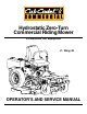
Hydrostatic Zero-Turn Commercial Riding Mower Professional Turf Equipment Z - Wing 48 OPERATOR’S AND SERVICE MANUAL
TABLE OF CONTENTS Foreword. . . . . . . . . . . . . . . . . . . . . . . . . . . . . . . . . . . . . . . . . . . . . . . . . . . . . . . . . . . . . . . 3 General Safety Operations . . . . . . . . . . . . . . . . . . . . . . . . . . . . . . . . . . . . . . . . . . . . . . . . . 4 A.Danger . . . . . . . . . . . . . . . . . . . . . . . . . . . . . . . . . . . . . . . . . . . . . . . . . . . . . . . . . . 4 B. Warning . . . . . . . . . . . . . . . . . . . . . . . . . . . . . . . . . . . . . . . . . . . . . . .
FORWARD The Z-Wing 48 Hydrostatic Zero-Turn Commercial Riding Mower provides superb maneuverability, mid-mount cutting capability for professional landscapers, commercial lawn service companies, professional turf managers and golf course superintendents. The machine incorporates many safety features that should be studied by all operators and maintenance personnel before use. The list of safety precautions should receive particular attention.
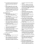
GENERAL SAFETY OPERATIONS 4. 5. A. DANGER 1. 2. 3. 4. 6. Do not operate machine in confined areas where exhaust gases can accumulate. Do not operate machine without mower chute deflector in place and operational. Do not carry passengers. This is a narrow track Zero-Turn mower, and it should not be operated on steep slopes. Refer to slope gauge on page 28. 7. 8. 9. B. WARNING 10. 1. Do not operate machines under the influence of alcohol or drugs. 2.
10. Lead-acid batteries generate hydrogen and oxygen gases which form an explosive mixture. Keep sparks and flames away at all times. 11. When looking for oil leaks, never run your hand over hydraulic hoses, lines or fittings. Never tighten or adjust hydraulic hoses, lines or fittings while the system is under pressure. If high-pressure oil penetrates the skin, the oil must be removed within a few hours by a doctor familiar with this form of injury or serious complications may result. 3. 4. 5. 6. 7. B.
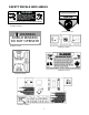
SAFETY DECALS AND LABELS TO R E D U C E T H E R I S K O F I N J U R Y, D O N OT O P E R ATE M OW E R U N L E S S DISCHARGE CHUTE COVER OR GRASS C AT C H E R I S I N I T S PR O P E R P L A C E . DANGER KEEP HANDS AND FEET AWAY. DO NOT OPERATE MOWER UNLESS CHUTE DEFLECTOR OR ENTIRE GRASS CATCHER IS IN ITS PROPER PLACE. DANGER KEEP HANDS and FEET AWAY S30503 ASSEMBLE CHUTE DEFLECTOR TO THIS UNIT BEFORE OPERATING.
SPECIFICATIONS Engine: Type: Air Cleaner: Lube System: Starter: Traction Drive: Hydraulic Tank: Cutter Deck;Drive: Clutch: Deck Lift: Cutting Height: No.
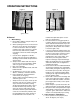
OPERATING INSTRUCTIONS Figure. 1 Electric Blade Clutch Switch Figure. 2 Tach and Hour Meter Engine throttle Choke Lever Ignition Switch A.General maintain the uphill side lap bar “essentially” in a fixed position. k. Be careful when crossing gravel paths or roadways. Always turn off the blade clutch switch and wait until the blades stop rotating and raise the cutting deck to the transport position. Always allow other vehicles to have the right of way. l.
B.Controls b. Avoid turning downhill if possible, if not use extra care and go slowly. c. Avoid turning when going downhill, traction is at a minimum going downhill. d. Do not operate with discharge side of the mower toward streets, buildings, playgrounds, parking lots, other machines, animals, and other people. e. Avoid operation or use extreme care if the traction surface is wet, unstable, or slippery. f.
Deck Lift Handle Steering Levers Brake Figure. 4 Fuel Shutoff Valve Figure. 3 9. Digital Tachometer and Hour Meter: (See Figure 1) Located on the seat support above the ignition switch. When the machine is running the tachometer displays engine rpm. When the machine is off the tachometer displays running time. 4. Electric Blade Clutch Switch: (See Figure 1.) Located on the seat support beside the ignition switch.
C.Initial Adjustments Follow the procedures below to set the appropriate pitch angle to the mowing deck. a. Park the mower on a flat paved surface, engage the parking brake, shut off the engine, remove the key from the ignition switch, remove connection of the spark plugs and using the transport lever, lower the mowing deck into the cutting position. b.
stop running. Move the lap bars back to the neutral position and the engine should run. 2. Repeat this procedure with the opposite side lap bars. 3. With the park brake engaged and the lap bars in the neutral position, advance the engine speed control completely forward (Hi-idle), engage the PTO control switch (pull upward), then lift off the seat — the engine should stop running. Sit down and the engine should run. Turn off the PTO by pushing the control switch down. 4.
Release both lap bars and the machine should stop turning. 3. To turn counter-clockwise, slowly move the RIGHT lap bar forward while simultaneously moving the LEFT lap bar rearward. Release both lap bars and the machine should stop turning (this is a safety check, the normal procedure is for the operator to slowly bring the lap bars to the neutral position). 3. Start the Engine: a. Open the fuel shutoff valve. b. Sit on the Seat. Set the parking brake “On”. c.
f. MAINTENANCE AND SERVICE Fold in the steering levers to the operating position. WARNING: WARNING: When operating this mower forward, do not allow the steering levers to return to the neutral position on their own. Always maintain a firm grip on the steering levers, operate them smoothly and avoid any sudden movements of the levers when starting or stopping.
Hair Pins Figure. 5 h. Sharpen the pivot blades as part of the blade assembly, so that the balance of the assembly can be checked. Sharpen blades evenly at the original 30° angle to maintain balanced cutting blades. Do not sharpen the underside of the blades. Use a electric blade sharpener, a conventional electric grinder or a hand file to sharpen the blades. i. Replace any blade with severe nicks or dents that cannot be removed by filing. j.
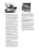
Figure. 7 Spindle 1. Hydraulic Tank Adding Hydraulic Oil (5W40 full synthetic) Place the Mower on a level surface and engage the parking brake. b. Stop the engine and remove the key from the ignition switch. c. Clean the area around the Hydraulic Oil fill neck. d. Remove the hydraulic fill cap and check the level. The correct level is up to the lowest hole of the oil tank fill neck. e. Pour hydraulic oil into the reservoir up to the lowest hole in the oil tank fill neck, if necessary. a. Figure. 6 d.
c. caps and drain oil from both left and right pumps. Replace and retighten nuts. Hydraulic pumps Unfasten hose and drain from this side of both pumps. Store the battery with a full charge. A discharged battery will freeze (refer to the table below). Specific Gravity Freezing Temp (°F) 1.265 -71 1.250 -62 1.200 -16 1.150 5 1.100 16 Figure. 8 d. Recharge battery when ever the specific gravity value is less than 1.225 3. Battery Removal j. Coat new filter seal with oil before installation.
feeler gage (0.013" to 0.015") into each slot as the air gap adjustment nut are tightened. The correct adjustment occurs when slight contact with the feeler gage occurs. Engage the BBC a couple of times, and recheck the air-gap. If it is not between 0.013" and 0.015", repeat the adjustment procedure. b. Parking Brake Switch: Sit in the operator’s seat. With both steering levers opened-out in the neutral position and the blade clutch switch “off”, release the parking brake and try to start the engine.
Use the Following guidelines for maintaining the tires: seat against spring pressure, and swing one of the steering levers up to the operating position. Release the operator’s seat and the engine should stop. If the engine does not stop, the seat switch must be replaced. With both steering levers folded out in the neutral position, the parking brake engaged and the blade clutch switch in the “off” position, sit in the operator’s seat and start the engine.
opened-out position. If your mower creeps do the following. a. Jack up rear of unit. b. Place Lapbars in neutral opened-out position. c. Locate jam nuts. (Reference control assembly in parts list). d. Loosen jam nuts on both ends of rod connectors. See Control Assembly in the Illustrated Parts Book (ONLY if mower creeps.) e. Start unit and push throttle all the way on. f. If unit creeps forward rotate rear rod connectors counter-clockwise. And if unit creeps in reverse, rotate clockwise. 1.
rear. To make the adjustment, place the steering levers in the opened-out neutral position and set the parking brake, shutoff the engine, take the key from the ignition switch and pivot the seat forward. If the mower creeps to the right, you will adjust the linkage on the left side of the mower and vice-versa. Remove the cap screw and lock washer that secure the linkage control arm rod end bearing to the control lever pivot. Loosen the jam nut which prevents the rod end bearing from turning.
e. Check the tires and tire pressure. Drive Tires: 10-12 psi. Front Caster Wheels: 20-25 psi. f. Check the spindle belt, the mower drive belt and the hydro drive belt. g. Check the blades. Make sure they are sharp and that the blade securing bolts and nuts are tight. h. Check the cutting height. 2. When ready to start the engine: a. Check the five safety switches for proper operation. 3. After mowing: a. Clean the mower. b. Clean the engine air screen. c. Oil the wear points. Follow the Oiling Chart. d.
. OIL CHART Apply a few drops of SAE 20W-50 engine oil or use a spray lubricant. Apply the oil to both sides of pivot points. Wipe off any excess. Start engine and operate mower briefly to insure that oil spreads evenly.
Performance Adjustments B. Enginge RPM Check and Adjustment A. High Speed Tracking Adjustment If mower tracks to one side with both lap bars in fully forward position: 1. 2. 3. 4. 5. 6. High RPM Spec. Low RPM Spec. 23 HP Kohler 3600 +/-50 1550 +/-100 NOTE: RPM Specs. are for free running engines under no load. 1. Check air pressure in all four tires: a. Pressure should be within specified ranges and balanced side-to-side. b. Rear tires 8-10 psi. recommended (20 psi MAX.) c.
C. Deck Corner Ball Wheel Roller Settings 4. 1. Matching the set heights of the ball rollers on the four corners of the mower deck to the desired cut height will prevent edge scalping and minimize any side-to-side variance in cut height. 2. There are three height adjustment holes in the bracket that mount the ball rollers to the deck. a. Use the top set of holes for cut heights of 2 inches or lower. b. c.
F. Deck leveling Procedure 1. 2. 3. 4. 5. 6. 7. 8. 2. Park the mower on a flat paved surface, engage the parking brake, shut off the engine, remove the key from the ignition switch, disconnect the spark plug wires and using the transport lever, lower the mowing deck into the 4" height of cut position. (The 4" height of cut position is recommended in order for one to see and obtain a measurement. Any height of cut position is acceptable as long as a proper measurement can be taken.
Front of Unit Left Side Point B Jam Nuts threaded bolt Jam Nut Right Side Figure.
WIRING DIAGRAM 28
SLOPE GAUGE USE THIS PAGE AS A GUIDE TO DETERMINE SLOPES WHERE YOU MAY NOT OPERATE SAFELY. SIGHT AND HOLD THIS LEVEL WITH A VERTICAL TREE A POWER POLE A 15 °S LOP E OR A FENCE POST A CORNER OF A BUILDING F O L D ON D O T TED LIN E , REP RE S E NTIN G 15° WARNING Do not mow on inclines with a slope in excess of 15 degrees (a rise of approximately 2-1/2 feet every 10 feet). A riding mower could overturn and cause serious injury.
MAINTENANCE RECORD DATE WORK PERFORMED DATE 30 WORK PERFORMED
MAINTENANCE RECORD DATE WORK PERFORMED DATE 31 WORK PERFORMED
MANUFACTURER’S LIMITED WARRANTY - TURF EQUIPMENT This warranty is specific to the product manual to which it is attached. For a complete list of products and warranties contact your authorized Cub Cadet Commercial dealer. Proper maintenance of the purchased Cub Cadet Commercial equipment is the owner’s responsibility. Follow the instructions in your owner’s manual for correct lubricants and maintenance schedule.