
Instruction Manual

Z-Force-S
56
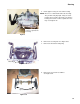
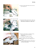
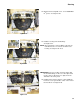
9. Separate the speed cam assemblies by driving out
the two roll pins using a 5/32” pin punch and a ham
-
mer. See Figure 6.35.
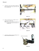
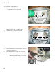
10. Slide the output bevel gear assemblies off of the
speed cams.
See Figure 6.36.
NOTE: Marking the left and right speed cams and
the left and right hydro arms will make reas
-
sembly easier.
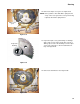
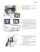
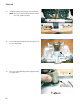
11. Separate the output bevel gear assembly by remov-
ing the snap ring. See Figure 6.37.
Figure 6.35
5/32” pin punch
Figure 6.36
Speed cam
Output bevel gear assembly
Hydro arm
Figure 6.37
Remove this snap ring