
Instruction Manual

Z-Force-S
8
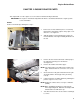
Brake adjustment
NOTE: When performing a brake adjustment, inspect the brake components for signs of wear or damage.
1. Block the front wheels.
2. Lift and safely support the rear of the mower.
NOTE: Make sure the parking brake is released.
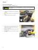
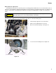
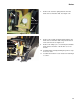
3. Remove the cotter pin locking the castle nut on the
brake caliper.
See Figure 3.3.
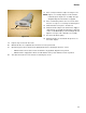
4. Back the castle nut off a few turns using a 9/16”
wrench.
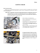
NOTE: Even if the brakes are set to the correct
clearance, inserting a feeler gauge between
the rotor and the brake puck can be very dif
-
ficult. Loosen the castle nut first, then insert
the feeler gauge and tighten the nut to set
the proper clearances
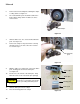
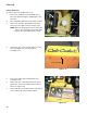
5. Insert a 0.030” (0.8 mm) feeler gauge between the
brake rotor and the outboard brake puck.
See Figure 3.4.
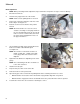
NOTE: The tolerance for the brake clearance is
0.020” - 0.040” (0.5 - 1.0mm). The 0.030
feeler gauge will set the clearance at the
midpoint.
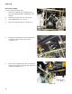
6. Tighten the nut until there is slight drag on the feeler
gauge.
NOTE: For even braking, both sides should be set
to the same clearance.
7. Install a new cotter pin.
8. Repeat same procedure on the other side.
9. Take the mower off of the jack stands.
10. Open the by-pass valves and check the parking brake before returning the mower to service.
• With the brakes released, the mower should have only hydraulic drag when it is pushed.
• With the brakes engaged, the wheels should slide before they rotate when the mower is pushed.
11. Test drive the mower in a safe area before returning it to service.
Figure 3.3
Castellated nut
Cotter pin
Figure 3.4
0.030” feeler
gauge