Safe Operation Practices • Set-Up • Operation • Maintenance • Service • Troubleshooting • Warranty Operator’s Manual Z-Force S60 & Z-Force S48 Commercial WARNING READ AND FOLLOW ALL SAFETY RULES AND INSTRUCTIONS IN THIS MANUAL BEFORE ATTEMPTING TO OPERATE THIS MACHINE. FAILURE TO COMPLY WITH THESE INSTRUCTIONS MAY RESULT IN PERSONAL INJURY. CUB CADET LLC, P.O. BOX 361131 CLEVELAND, OHIO 44136-0019 Printed In USA Form No.
1 To The Owner Thank You Thank you for purchasing a Cub Cadet Zero-Turn Tractor. It was carefully engineered to provide excellent performance when properly operated and maintained. If applicable, the power testing information used to establish the power rating of the engine equipped on this machine can be found at www.opei.org or the engine manufacturer’s web site. Please read this entire manual prior to operating the equipment.
Important Safe Operation Practices 2 WARNING! This symbol points out important safety instructions which, if not followed, could endanger the personal safety and/or property of yourself and others. Read and follow all instructions in this manual before attempting to operate this machine. Failure to comply with these instructions may result in personal injury. When you see this symbol.
12. A missing or damaged discharge cover can cause blade contact or thrown object injuries. 13. Stop the blade(s) when crossing gravel drives, walks, or roads and while not cutting grass. 14. Watch for traffic when operating near or crossing roadways. This machine is not intended for use on any public roadway. 15. Do not operate the machine while under the influence of alcohol or drugs. 16. Mow only in daylight or good artificial light. 17. Never carry passengers. 18. Back up slowly.
Children 1. Tragic accidents can occur if the operator is not alert to the presence of children. Children are often attracted to the machine and the mowing activity. They do not understand the dangers. Never assume that children will remain where you last saw them. a. b. c. d. e. Keep children out of the mowing area and in watchful care of a responsible adult other than the operator. Be alert and turn machine off if a child enters the area.
General Service 1. 2. Before cleaning, repairing, or inspecting, make certain the blade(s) and all moving parts have stopped. Disconnect the spark plug wire and ground against the engine to prevent unintended starting. 3. Periodically check to make sure the blades come to complete stop within approximately (5) five seconds after operating the blade disengagement control. If the blades do not stop within the this time frame, your machine should be serviced professionally by an authorized dealer. 4.
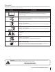
Safety Symbols This page depicts and describes safety symbols that may appear on this product. Read, understand, and follow all instructions on the machine before attempting to assemble and operate. Symbol Description READ THE OPERATOR’S MANUAL(S) Read, understand, and follow all instructions in the manual(s) before attempting to assemble and operate WARNING— ROTATING BLADES Do not put hands or feet near rotating parts or under the cutting deck. Contact with the blade(s) can amputate hands and feet.
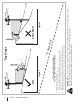
Section 2 — Safe Operation Practices Figure 1 line Figure 2 (TOO STEEP) 15° Slope WARNING! Slopes are a major factor related to tip-over and roll-over accidents which can result in severe injury or death. Do not operate machine on slopes in excess of 15 degrees. All slopes require extra caution. Always mow across the face of slopes, never up and down slopes. To check the slope, proceed as follows: 1. Remove this page and fold along the dashed line. 2.
3 Assembly & Set-Up Contents of Crate • • One Lawn Tractor • One Oil Drain Hose • One Z-Force S Operator’s Manual • One Engine Operator’s Manual One Deck Wash Hose Coupler Tractor Preparation Steering Wheel 1. Remove the upper crating material from the shipping pallet, and cut any bands or tie straps securing the tractor to the pallet. 1. Remove the hardware for attaching the steering wheel from beneath the steering wheel cap.
2. Remove the two shoulder bolts and lock nuts in the seat pan as shown in Figure 3-3. Adjusting the Seat To adjust the position of the seat, push the seat adjustment lever to the left. Slide the seat forward or rearward to the desired position; then release the adjustment lever. Make sure seat is locked into position before operating the tractor. See Figure 3-5. Figure 3-3 3. Rotate the seat into position and secure the seat into place with the previously removed shoulder bolts and lock nuts.
2. Install the hitch bracket and muffler mount bracket as shown in Figure 3-7 and secure with the hex flange screws and flange lock nuts removed in step 1. Connecting the Battery Cables CALIFORNIA PROPOSITION 65 WARNING! Battery posts, terminals, and related accessories contain lead and lead compounds, chemicals known to the State of California to cause cancer and reproductive harm. Wash hands after handling.
4 Controls & Features Cup Holder Ignition Switch Hour Meter/ Indicator Panel Fuel Tank Cap Parking Break PTO Switch Engagement Lever Index Plate Deck Lift Pedal Choke Control Throttle Control Seat Adjustment Lever Drive Pedal Reverse Pedal NOTE: References to LEFT, RIGHT, FRONT, and REAR indicate that position on the tractor when facing forward while seated in the operator’s seat.
PTO (Power Take-Off ) Switch Indicator Panel Features The PTO switch is located on the LH console to the left of the operator’s seat. Battery Indicator Illuminates and the battery voltage is displayed briefly when the ignition switch it turned to the “ON” position. The PTO switch operates the electric PTO clutch mounted on the bottom of the engine crankshaft. Pull the switch knob upward to engage the PTO clutch, or push the knob downward to disengage the clutch.
Choke Control Transmission Oil Expansion Reservoir (Not Shown) The choke knob controls the position of the engine choke and is located on the RH console. Pull the knob out to choke the engine; push the knob in to open the choke. CHOKE Parking Brake Engagement Lever The transmission oil expansion reservoir is connected by hoses to the RH and LH transmission assemblies, and is located behind the seat box.
5 Operation General Safety Before Operating Your Tractor • RECEIVE INSTRUCTION — Entirely read this operator’s manual. Learn to operate this machine SAFELY. Do not risk INJURY or DEATH. Allow only those who have become competent in its usage to operate this tractor. • Before you operate the tractor, study this manual carefully to familiarize yourself with the operation of all the instruments and controls. It has been prepared to help you operate and maintain your tractor efficiently.
Engaging the PTO Engaging the PTO transfers power to the cutting deck or other (separately available) attachments. To engage the PTO: 1. Move the throttle control lever to the FAST 2. Pull the PTO/Blade Engage knob outward into the engaged (ON) position. See Figure 5-1. OFF 1. Operator must be sitting in the tractor seat. 2. Engage the parking brake. Refer to Figure 5-2. position. ON PTO Down Engage the Parking Brake Figure 5-2 3.
8. Allow the engine to run for a few minutes at mid-throttle before putting the engine under load. 9. Observe the hour meter/indicator panel. If the battery indicator light or oil pressure light come on, immediately stop the engine. Have the tractor inspected by your Cub Cadet dealer. Cold Weather Starting When starting the engine at temperatures near or below freezing, ensure the correct viscosity motor oil is used in the engine and the battery is fully charged. Start the engine as follows: 1.
Driving On Slopes Refer to the SLOPE GAUGE on page 8 to help determine slopes where you may operate the tractor safely. WARNING! Do not mow on inclines with a slope in excess of 15 degrees (a rise of approximately 2-1⁄2 feet every 10 feet). The tractor could overturn and cause serious injury. • Mow across slopes, not up and down. • Exercise extreme caution when changing direction on slopes. • Watch for holes, ruts, bumps, rocks, or other hidden objects. Uneven terrain could overturn the machine.
6 Maintenance & Adjustments Maintenance Schedule Before Each use Every 10 Hours P Clean Battery Terminals P Lube Front Caster Wheels and Wheel Spindles Check Engine Cooling Fins for Debris (Clean as Necessary) Every 25 Hours P P Lube Deck Spindles P Lube Pedal Pivot Points Maintenance Prior to Storing P P P P P Battery Storage 1. When storing the tractor for extended periods, disconnect the negative battery cable. It is not necessary to remove the battery. 2.
b. c. Using a fuel stabilizer such as STA-BIL® for storage between 30 and 90 days: • Read the product manufacturer’s instructions and recommendations. • Add to clean, fresh gasoline the correct amount of stabilizer for the capacity (approximately 3 gallons) of the fuel system. • Fill the fuel tank with treated fuel and run the engine for 2-3 minutes to get stabilized fuel into the carburetor. 1.
3. Attach the hose coupler to the water port on your decks surface. See Figure 6-2. Lubrication Nozzle Adapter Front Wheels Deck Wash Nozzle Adapter Lock Collar WARNING! Before lubricating, repairing, or inspecting, always disengage PTO, set parking brake, stop engine and remove key to prevent unintended starting. Each of the front wheel spindles and rims is equipped with a grease fitting. See Figure 6-3. Lubricate with a No.
Deck Spindle Grease fittings can be found on top of each spindle bolt. See Figure 6-4 for the Z-Force S60 and Figure 6-5 for the Z-Force S48. Lubricate with 251H EP grease or an equivalent No. 2 multipurpose lithium grease. Using a grease gun, apply two strokes (minimum) or sufficient grease to the spindle shaft. Grease Fittings Adjustments NOTE: Check the tractor’s tire pressure before performing any deck leveling adjustments. Refer to Tires on page 22 for information regarding tire pressure.
Leveling the Deck (Front To Rear) Setting the Deck Wheels NOTE: Check the tractor’s tire pressure before performing any deck leveling adjustments. Refer to Tires on page 22 for information regarding tire pressure. Always level the deck side to side before front to rear. Move the tractor on a firm and level surface, preferably pavement, and proceed as follows The front of the deck should be between 1⁄4” and 3⁄8” lower than the rear of the deck. Adjust if necessary as follows: 1.
Rear Deck Rollers The rear deck rollers can be placed in two positions. To change the height of the rear deck rollers Refer to Figure 6-9 and proceed as follows: Upper Hex Screw Lower Hex Screw Upper Flange Lock Nut Figure 6-9 1. Loosen — but do not remove — the lower hex screws and lower flange lock nuts on all three brackets securing the rollers to the deck. NOTE: The brackets are slotted on the lower half of the bracket to allow the deck rollers to be moved up and down. 2.
7 Service WARNING! Before performing any service, place the PTO switch in the “OFF” position, engage the parking brake lever, turn the ignition key to the “OFF” position and remove the key from the switch. Charging the Battery Test and, if necessary, recharge the battery after the tractor has been stored for a period of time. • Battery Removal WARNING! Battery posts, terminals and related accessories contain lead and lead compounds. Wash hands after handling. A voltmeter or load tester should read 12.
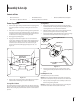
Deck Removal Idler Pulley Bracket Remove the mower deck from the tractor as follows: 1. Move the tractor to a level surface, disengage the PTO, stop the engine, and set the parking brake. 2. Remove the lock rod by pressing the pedal forward to release tension then rotate the lock rod until the end of the rod points upward and slide it out of the deck height bracket. See Figure 7-3. Idler Pulley Idler Pulley PTO Pulley Lock Rod Figure 7-5 Lowest Mowing Position 5.
Deck Installation Install the deck on the tractor as follows: 1. Place the deck lift pedal in the highest mowing position and secure it by placing the lock rod behind the pedal. See Figure 7-3. 2. Slide the deck under the tractor on the right side of the tractor lining up the deck lift adjustment brackets and the deck lift brackets on the deck. See Figure 7-7. 5. After all four cotter pins are secure, slide the deck forward and hook the deck to the U-rod. 6.
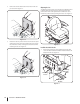
Replacing the Belt Mower Blade Care 1. Remove the deck from beneath the tractor, (refer to Deck Removal on page 26). 2. Pull the four draw latches up and away from the deck covers to unlatch and remove both covers. See Figure 7-11 for the Z-Force S60 and Figure 7-12 for the Z-Force S48. Draw Latches WARNING! Protect your hands by using heavy gloves when handling the blades. When servicing the mower deck, be careful not to cut yourself on the sharpened blades.
Sharpening the Blades Changing the Spindle Assembly 1. Remove the deck from beneath the tractor, (refer to Deck Removal on page 26) then gently flip the deck over to expose its underside. 1. Remove the deck from beneath the tractor, (refer to Deck Removal on page 26). 1. Clean any debris from the blades. Keep blades sharp and free of build up at all times. 2. Remove the hex washer screws securing the belt covers to the deck and remove the belt from the spindle pulleys. Refer to Figure 7-13. 2.
8 Troubleshooting Problem Excessive vibration Uneven cut Mower will not mulch grass (If Equipped w/Mulching Kit) 30 Cause Remedy 1. Cutting blade loose or unbalanced. 1. Tighten blade and spindle. 2. Damaged or bent cutting blade. 2. Replace blade. 1. Deck not leveled properly. 1. Perform side-to-side deck adjustment. 2. Dull blade. 2. Sharpen or replace blade. 3. Uneven tire pressure. 3. Check tire pressure in all four tires. 1. Engine speed too low. 1. Place throttle in FAST position.
9 Replacement Parts Component Part Number and Description 01005376 Deck Belt (Z-Force S60) 954-04262 PTO Belt (Z-Force S60) 954-3092A Drive Belt 954-04044A Deck Belt (Z-Force S48) 942-04415 942-04417 Mowing Blade (Z-Force S60) Mowing Blade (Z-Force S48) 918-3129C Deck Spindle 634-3159 734-04155 Deck Wheel (Z-Force S60) Deck Wheel (Z-Force S48) 925-1707D Battery 951-12193A Gas Cap 31
Component 32 Section 9 — Replacement Parts Part Number and Description 946-1086 Throttle Control Cable 946-04752 Choke Control Cable 925-2054A Ignition Key 01006693P Chute Deflector 634-04698 Wheel Assembly 634-04623 Caster Wheel Assembly
10 Attachments & Accessories Part No.
FEDERAL and/or CALIFORNIA EMISSION CONTROL WARRANTY STATEMENT YOUR WARRANTY RIGHTS AND OBLIGATIONS MTD Consumer Group Inc, the United States Environmental Protection Agency (EPA), and, for those products certified for sale in the state of California, the California Air Resources Board (CARB) are pleased to explain the emission (evaporative and/or exhaust) control system (ECS) warranty on your outdoor 2006 and later small off-road spark-ignited engine and equipment (outdoor equipment engine) In California, n
10. Add-on or modified parts that are not exempted by the Air Resources Board may not be used. The use of any non-exempted add-on or modified parts by the ultimate purchaser will be grounds for disallowing a warranty claims. MTD Consumer Group Inc will not be liable to warrant failures of warranted parts caused by the use of a non-exempted add-on or modified part.
CUB CADET LLC MANUFACTURER’S LIMITED WARRANTY FOR Z-FORCE COMMERCIAL ZERO-TURN COMMERCIAL RIDING MOWERS IMPORTANT: To obtain warranty coverage owner must present an original proof of purchase and applicable maintenance records to the servicing dealer. Please see the operator’s manual for information on required maintenance and service intervals.