Safe Operation Practices « Assembly Operation + Service And Maintenance OPERATOR'S MANUAL Front Engine Lawn Tractor English os — cores data os SORES ROSES compressor consciousnesses 1 Spanish (Espionage} Hess ran RPA SERRA coe ne Jo— 0X French (Francis) o senselessness PGE TA Record Product Information Mode! Number Before setting up and operating your new equipment, please locate the model plate on the equipment and record the information in the provided area to the right.
SAFE OPERATION PRACTICES A WARNING safety and/or property of yourself and others, Read and follow all instructions in this manual before attempting te operate this machine. Failure te comply with these instructions may result in personal injury. When you see this symbol, HEED ITS WARNING! (} This symbol points out important safety instructions which, if not followed, could endanger the personal result in serious injury or death.
SAFE OPERATION PRACTICES 7. Never leave a running tractor unattended, Always tum off blade, set the parking brake, stop the engine, and remove the hey before dismounting. 8, Disengage blade(s), set the parking brake, stop engine, and Walt until the blades] come to a complete stop before removing grass catcher, emptying grass, unclogging chute, removing any grass or deliriums, or making any adjustments. 9. Your tractor s designed to cut normal residential grass of a freight no more than 10° (25 cm).
SAFE OPERATION PRACTICES 8. Use extra care while operating tractor with grass catcher or other attachment(s). They can affect the stability of the tractor. Do not use grass catcher on slopes greater than 10° 9. De not try to stabilize the tractor by putting your futon the ground. 18. Keep all movement on slopes slow and gradual. De not make sudden changes In speed or direction.
SAFE OPERATION PRACTICES SERVICE 1. Keep machine in good working order. Do not use the factor until worn or damaged parts are replaced, 2. To avoid serious injury or death, do not modify engine in any way. Tampering with the governor setting can lead to 3 runaway engine and cause it to operate at unsafe speeds. Never tamper with factory setting of engine governor. Do not change the engine governor settings or over-speed the engine. The governor controls the maximum safe repeating speed of the engine. 3.
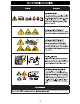
SAFE OPERATION PRACTICES SAFETY SYMBOLS This page depicts and describes safety symbols that MAY APPEAR on this product. Se BY VIRGINIA READ OPERATOR'S MANUAL Read, understand, and follow all the safety rules and Instructions in the manuals) and on the tractor before @ 5 attempting to operate this actor. Fall re to comply 3 with this information may result in personal injury or = i death. Keep this manual in a safe location for future and regular reference.
SAFE OPERATION PRACTICES NT natal EARNING AVOID FIRES Your tractor is designed to cut normal residential grass of heighten mere than 10° (25 om). Do net attempt to mow through unusually tall, dry grass {eg., pasture} or piles of dry leaves. Allie tractor to cool at least five minutes before fueling or storing inside an enclosed garage of storage shad, WARNING AVOID AMPUTATION BURY Do not put hands or feet near or under the anteing ded.
LAST MOTE: This Operators Manual covers several models. Tractor features may vary by model. Hot afl features in this manual are applicable ta all tractor models and the tractor depicted may differ from yous. MOTE: All refer antes in this manual to the left or right side and front or back of the tractor are from the operating position only. Exceptions, If any, will be specified, Preparation MANUALLY MOVING THE TRACTOR 1. Engage the transmission bypass rod to move the tractor manually without starting it.
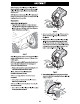
ASSEMBLY INSTALLING THE HOOD COLLAR (IF NECESSARY) ‘There are three (3) alignment pests (a) on the hued collar {b) that line up with corresponding alignment holes {2} in the hood {d). See Figure 5. Figure 5 lies these alignment points to properly position the hood collar {a}, then secure it in place with the six hex bolts (b) provided in the hardware bag. Tighten the hex bolts to 102-124 info (11.514 H-m}. See Figure §. Figure § INSTALLING THE SAP-ON HOOD TOPPER (IF NECESSARY) 1.
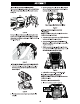
ASSEMBLE 2. With the rear tabs Installed, Insert the front tabs (2) on the plenum (b) as shown in Figure 11. Figure 11 NOTE: The rear tabs fit into a recessed area on the top of the hood, They side up from under the hood and into these recessed ares. 3. Push up on the bottom of the plenum to make size that the plenum is securely in place. 4, Secure the headlight shames {3} into the two guides (b) on the front of the plenum. Figure 12.
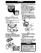
Lad] The hardware for attaching the front bumper is shipped Installed inch the bumper. 1. Remove the four hex screws (a) from the bumper {b), See Figure 15. 2. Position the bumper brackets ta the inside of the tractor’s frame and secures it in place with the four hex screws (a). See Figure 15, Figure 17 LOWER DECK DISCHARGE CHUTE DEFLECTOR rein Ever apostate the mower deck without the chute deflects installed and in the down position. For 46° deck models: 1.
LAST For deck models: 1 Check the tractor deck for 3 shipping brace that may be holding the chute deflector upward for shipment, If the brace Is present, it must be removed before operating the tractor. Holding the chute deflector fully upward, remove the shipping brace, Lower the chute deflector and discard the shipping brace. See Figure 19. Figure 18 SETTING THE DECK WHEELS HOT: The deck wheels are an anti-scalp feature of the deck and are not designed to support the weight of the cutting deck.
A CAUTION When attaching battery cables, always connect the POSITIVE {Red} wire to terminal first, followed by the NEGATIVE {Black} wire, HOT: The positive battery terminal 1s marked Pes. The negative battery terminal is marked Neg. CONNECTING THE BATTERY CABLES Lue Brays connect the positive lead to the battery before the negative (ead. This will prevent sparking or possible injury from an electrical short caused by contacting the tractor body with tools being used to connect cables.
LAST BATTERY REMOVAL Jeri Battery posts, te Is, and related accessories tantalum chad and lead compounds. Wash hands after handle The battery is located beneath the seat frame. To remove the battery: 1. Remove the hex screw and square nut securing the Mack negative battery lead to the negative battery post {marked BEG (3). Move the cable away from the negative battery post. 1. Remove the hex screw and square aut securing the red positive battery lead tithe positive battery post marked POS 3.
OPERATION Figure 24 NOTE: This Operator's Manual covers several models, Tractor D. THROTTLE/CHOKE (CONTROL LEVER, features may vary by model. Not all features in this manual are THROTTLE CONTROL, OR ELECTRONIC applicable to all tractor models and the tractor depicted may ’ Afr from yours, GOVERNOR CONTROL 1.
OPERATION 3. Electronic Governor Contra! {if equipped) When set in a given position, a uniform engine speed will be maintained. The electronic governor contra! has various Inputs for maintaining engine speed. Use CUT setting for optimal cutting performance in normal taunting conditions. Use POWER CUT setting for optimal cutting performance in heavy cutting conditions.
OPERATION I. PTO (BLADE ENGAGE] LEVER (MANUAL PTO) Low oil Activating the PTO (Blade Engage} Lever engages power to the NOTE: The law oil pressure function only works if the engine is cutting decor other {separately available} attachments. See equipped with an oil pressure switch. Engaging the P10 (Blade Engage} (Manual PRO tractors) section The screen will stalemate the letters 0" followed by “OIL, for information and instructions on using the PTO.
OPERATION P. DIFFERENTIAL LOCK PEDAL (IF EQUIPPED) titivating the differential lode increases traction by maintaining equal wheel speed on the rear tires, Ses Using the Differential Lock section for more information on using the differential fod. Q. SEAT ADJUSTMENT LEVER The seat adjustment lever allows for adjustment forward or backward of the operator's seat. Refer to the Assembly section for instructions on adjusting the seat position.
OPERATION Do not hold the keying the START position for longer than ten seconds at a time. Doing so may cause damage to your engine's electric starter. 7. Ashe engine warms up, disengage the choke control. Do not use the choke control to enrich the fue! moisture, except as necessary to start the engine. 8.
OPERATION USING JUMPER CABLES TO START ENGINE Set Batteries contain sulfuric acd and produce plosive gases, Make certain the area is well ventilated, wear gloves and eye protection, and avoid sparks or flames Rear the battery. If the battery charge is net sufficient to crank the engine, recharge the battery. If battery charger is unavailable and the tractor must be started, the aid of 2 booster battery will be necessary. {connect the booster battery as follows: 1.
OPERATION 2. Press down on the park canebrake control lever and hold it in that position. 3. Remove your foot from the forward drive pedal, 4. Release pressure from the park brakemen control lever, The forward drive pedal should remain in the down position nd the tractor will maintain the muse forward drive speed, fit doesn’t, the cruise control! is not engaged. Repeat Steps 1-4 again to engage the cruise contrive.
OPERATION . Once activated (indicator light ON), the tractor can ba driven in reverse with the cutting PT0 (Blade Engage) Lever in the engaged (ON) position, . Always IPO down and behind before and while backing ta triter sure na children ave around. After resuming forward mason, press the REVERSE CAUTION MODE button te rectum to NORMAL MOWING. The REVERSE CAUTION MODE will remain activated until: ‘The REVERSE CAUTION MODE button is pressed again.
OPERATION Do NOT attempt to mow heavy brush and weeds of extremely tall grass. Your tractor is designed to mow lawns, NOT clear brush. + Keep the blades sharp and replace the blades when wom. + Hen approaching the other end of the strip, slow down or stop before turning. A three point turn is recommended, «Align the tractor with an edge of the mowed strip and overlap approximately 3° (76 cml. «Direct the tractor on each subsequent strip to align with previously cut strip.
SERVICE AND MAINTENANCE Follow the Maintenance Schedule given below. This chart Sg § describes service guidelines only, Before performing any type of malntenance/service, disengage all controls and stop the engine. Wait until al Refer to the Engine Operator's Manual for engine maintenance items listed in the table below. ‘meting parts have come te a complete stop, Allow the engine te coal.
SERVICE AND MAINTENANCE Before| After | Every | Every | Every | Every | Every Priests Sea Engine Each | First] 200 Storm Operator's Use | Hours | Hours | Hours | Hours | Hours | Hows 5) Manual Cheer Fuel System (Lines, Tan, Cap, Fittings} Check Spark Arrest or Replace Oi Filter Vv Vv v Clean or Change Alf Filter Vv Vv Replace Fuel Filter Vv Vv Have Valve Lash Checked v & Adjusted ® Have this item performed by an authorized service dealer, VOTE: This Operator's Manual covers several models.
SERVICE AND MAINTENANCE VOTE: Using a pressure washer or garden hose is not recommended for cleaning your tractor other than to clean the underside of the deck. It may cause damage to electrical components, spindles, pulleys, bearings or the engine, The use of eater will result in shortened life and reduce serviceability. «Clean under the hood, including exhaust manifold, around fuses, all wiring and ha messes, muffler pipe, muffler shield, engine intake screens and Colin ding, etc. See Figure 30.
SERVICE AND MAINTENANCE To complete an oll change, proceed as follows: 1. Fun the engine for a short time to warm the engine oll. The ofl will flow more freely and carry away more impurities, Use care to avoid burns from het ol, 2. (pen the tractors hood and locate the oil drain port on the side of the engine, 3. Place an appropriate ofl collection container with at least a 2.5 quart {2.36 1) capacity below the opening of the oil drain tube, to collect the used oil.
SERVICE AND MAINTENANCE Spark Harvest Maintenance {if equipped) Spark ancestor assemblies must be inspected and cleaned periodically (see the Maintenance Schedule charting this manual). Visually inspect the screen for tears, broken wires or loose welds, Replace the spark ancestor assembly if any of these conditions exist. if the screen is in good condition, dean the seen by brushing away loose dire or carbon particles. Tires Keep the tires inflated to the recommended pressures.
SERVICE AND MAINTENANCE LEVELING THE DECK {SIDE-TO-SIDE} 1. With the tractor parked on a firm, level surface, plate the desk lift lever in the middies position and rotate both blades so that they are perpendicular with the tractor. 2. Measure the distance from the outside of the left blade tip to the ground and the distance from the outside of the right blade tip to the ground. Both measurements taken should be equal. if they are not, proceed to the next step. 3.
SERVICE AND MAINTENANCE PARK BRAKE ADJUSTMENT if the tractor does not come to a complete stop when the brake pedal is completely depressed, or if the tractor’s rear wheels can coll with the park brake applied (and the hydro static relief naive open], the brake is in need of adjustment.
SERVICE AND MAINTENANCE Figure 42 Figure 44 15. Move the deck lift lever into the top notch to raise the deck 5. When the hole in the center of the blade aligns with the 18% up and out of the way. tractor blade retainer, carefully lower the blade, See Figure 45. 16. Gently slide the deck cut from underneath the tractor. Removing the Blades Se Shut the engine off and remove ignition key before Tempting the cutting blade(s) for sharpening or replacement.
SERVICE AND MAINTENANCE STANDARD BLADE SYSTEM WITH S-BLADES (OF EQUIPPED) 1 Remove the deck from beneath the tractor, referrer Deck Removal} then gently flip the deck over to expose ts underside. Use 2 15/16" wrench to hold the hex nut on top of the spindle assembly when loosening the hex nut (3) and washer (d)* securing the blade (b}.
SERVICE AND MAINTENANCE 2. When re-installing blades, be sure of the following {see Figure 47 on page 32): a, Blades (b) are installed so that wings are pointing upward toward the top of the deck. bs. Washer (d)* is placed between bottom of blade (b) and hex nut (2), IMPORTANT! Skiing *5 shaped cutout with matching °S” shape on spindle for secure fit. 3. Tighten hex nits {3) to 70-90 ft-lbs (95-122 H-m). 4. Re-install the deck (refer to Deck Installation in this section). Sharpening the Blade 1.
SERVICE AND MAINTENANCE 7. Re-install the deck making sure the belt remains routed around the pulleys as instructed. , On manual PTO units, re-install the engine pulley keeper red and the FTO cable. . Pull the right side of the belt and place the narrow side of the belt into the PT) pulley, See Figure 55, 10. While holding the belt and pulley together, rotate the pulley tithe left. Continue holding and rotating the pulley and belt until the belt is fully rolled into the PTO pulley.
SERVICE AND MAINTENANCE Troubleshooting Before performing any type of maintenance/servics, disengage all controls and stop the engine. Walt unt Jl moving parts have come io a complete stop. Disconnect spark plies wire and ground it against the engine to prevent unintended starting. Always wear safety glasses during operation or while performing any adjustments or replays. THIS SECTION ADDRESSES MINOR SERVICE ISSUES.