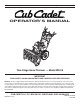
Safety • Assembly • Operation • Adjustments • Maintenance • Troubleshooting • Parts Lists • Warranty OPERATOR’S MANUAL Two-Stage Snow Thrower — Model WE 26 IMPORTANT READ SAFETY RULES AND INSTRUCTIONS CAREFULLY BEFORE OPERATION Warning: This unit is equipped with an internal combustion engine and should not be used on or near any unimproved forest-covered, brushcovered or grass-covered land unless the engine’s exhaust system is equipped with a spark arrester meeting applicable local or state laws (if any)
This Operator’s Manual is an important part of your new snow thrower. It will help you assemble, prepare and maintain the unit for best performance. Please read and understand what it says. Table of Contents Customer Support............................................... 2 Safety Labels....................................................... 3 Safe Operation Practices.................................... 4 Setting Up Your Snow Thrower........................... 6 Operating Your Snow Thrower..................
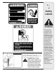
1 Safety Labels WARNING This symbol points out important safety instructions which, if not followed, could endanger the personal safety and/or property of yourself and others. Read and follow all instructions in this manual before attempting to operate this machine. Failure to comply with these instructions may result in personal injury. When you see this symbol. HEED ITS WARNING! A chute clean-out tool is fastened to the top of the auger housing with a mounting clip.
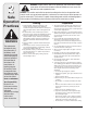
2 Safe Operation Practices WARNING This symbol points out important safety instructions which, if not followed, could endanger the personal safety and/or property of yourself and others. Read and follow all instructions in this manual before attempting to operate this machine. Failure to comply with these instructions may result in personal injury. When you see this symbol.
Operation Maintenance & Storage 1. Do not put hands or feet near rotating parts, in the auger/impeller housing or chute assembly. Contact with the rotating parts can amputate hands and feet. 2. The auger/impeller control lever is a safety device. Never bypass its operation. Doing so makes the machine unsafe and may cause personal injury. 3. The control levers must operate easily in both directions and automatically return to the disengaged position when released. 4.
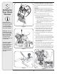
3 Setting Up Your Snow Thrower This Operator’s Manual may cover a range of product specifications. Characteristics and features discussed and/or illustrated in this manual may not be applicable to all models. IMPORTANT: Two replacement auger shear pins are included with this manual (or stowed in the plastic handle panel). Refer to “Augers” section in the Maintenance section for more information regarding shear pin replacement. 1. Remove the unit from the crate or carton. A 2.
3 CAUTION: Prior to operating your snow thrower, refer to Auger Control Test in Operation section. Read and follow all instructions carefully, and perform all adjustments to verify your snow thrower is operating safely and properly. Setting Up Your Snow Thrower Shear Pin Storage Holes are located in the plastic dash panel for convenient shear pin storage. See Figure 7. IMPORTANT: This unit is shipped with the engine full of oil. After assembly, refer to engine manual for fuel and oil fill-up details.
4 Operating Your Snow Thrower Know Your Snow Thrower Shift Lever Drive Control Four-Way Chute Control™ Auger Control Electric Start Button Chute Assembly Gas Cap Oil Fill Engine Controls Clean-Out Tool Recoil Starter Handle Electric Starter Outlet Primer Ignition Key WARNING Choke Control Read, understand, and follow all instructions and warnings on the machine and in this manual before operating. Use extreme care when handling gasoline.
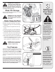
Auger Control Four-Way Chute Control™ The chute directional control is located on the left side of the dash panel. • To change the direction in which snow is thrown, squeeze the button on the joy-stick and pivot the joy-stick to the right or to the left. The auger control is located on the left handle. Squeeze the control grip against the handle to engage the augers and start snow throwing action. Release to stop.
4 Operating Your Snow Thrower Gas & Oil Fill-Up Service the engine with gasoline and oil as instructed in the Tecumseh Engine manual packed separately with your snow thrower. Read instructions carefully. Starting The Engine 1. Attach spark plug wire to spark plug. Make certain the metal loop on the end of the spark plug wire (inside the rubber boot) is fastened securely over the metal tip on the spark plug. 2. Make certain both the auger control and drive control are in the disengaged (released) position.
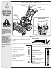
To Engage Drive 1. With the engine running near top speed, move shift lever to one of six FORWARD positions or two REVERSE positions. Select a speed appropriate for the snow conditions that exist. 2. Squeeze drive control against the right handle and the snow thrower will move. Release it and the drive motion will stop. 3. To turn the unit left or right, squeeze the respective wheel steering control. See Figure 12.
5 Shift Cable If the full range of speeds (forward and reverse) cannot be achieved, refer to the figure to the left and adjust the shift cable as follows: 1. Place the shift lever in the fastest forward speed position. Making Adjustments 2. Loosen the hex nut on the shift cable index bracket. See Figure 14. 3. Pivot the bracket downward to take up slack in the cable. 4. Retighten the hex nut. 5. Check for correct adjustment before operating the snow thrower.
5 You can also check the adjustment as follows: 1. With the snow thrower tipped forward (be certain to drain gasoline or place plastic film under the gas cap if the snow thrower has already been operated), remove the frame cover underneath the snow thrower by removing the self-tapping screws. Refer to Figure 22 in Maintenance section. Making Adjustments 2. With the drive control released, there must be 1/8" clearance between the friction wheel and the drive pulley in all positions of the shift lever. 3.
6 Maintaining Your Snow Thrower Engine Refer to the separate Tecumseh Engines manual packed with your unit for all engine maintenance. Lubrication Engine Refer to the separate Tecumseh Engines manual packed with your unit for all engine lubrication instructions. Gear Shaft The gear (hex) shaft should be lubricated at least once a season or after every 25 hours of operation. 1. Remove the lower frame cover by removing the two screws which secure it. 2.
1 Auger Belt Replacement To remove and replace your snow thrower’s auger belt, proceed as follows: 1. Remove the plastic belt cover on the front of the engine by removing the two self-tapping screws. NOTE: Drain the gasoline from the snow thrower, or place a piece of plastic under the gas cap. 2. Carefully pivot the snow thrower up and forward so that it rests on the auger housing. Remove the frame cover from the underside of the snow thrower by removing four self-tapping screws which secure it.
6 1 Augers • The augers are secured to the spiral shaft with two shear pins and cotter pins. If the auger should strike a foreign object or ice jam, the snow thrower is designed so that the pins may shear. Refer to Figure 9. • Maintaining Your Snow Thrower If the augers will not turn, check to see if the pins have sheared. One set of replacement shear pins has been provided with the snow thrower. When replacing pins, spray an oil lubricant into shaft before inserting new pins.
1 Friction Wheel Removal If the snow thrower fails to drive with the drive control engaged, and performing the drive control cable adjustment on page 14 fails to correct the problem, the friction wheel may need to be replaced. Follow the instructions below. Examine the friction wheel for signs of wear or cracking and replace if necessary • Place the shift lever in third Forward (F3) position. • Drain the gasoline from the snow thrower, or place a piece of plastic under the gas cap.
7 Off-Season Storage If the snow thrower will not be used for 30 days or longer, or if it is the end of the snow season when the last possibility of snow is gone, the equipment needs to be stored properly. Follow storage instructions below to ensure top performance from the snow thrower for many more years. Preparing Engine Preparing Snow Thrower NOTE: Refer to the engine manual for more detailed information on preparing the snow thrower engine for storage.
Problem Remedy Cause 1. Choke not in ON position. 1. Move choke to ON position. 2. Spark plug wire disconnected. 2. Connect wire to spark plug. 3. Fuel tank empty or stale fuel. 3. Fill tank with clean, fresh gasoline. 4. Engine not primed. 4. Prime engine as instructed in “Operating Your Snow Thrower”. 5. Faulty spark plug. 5. Clean, adjust gap, or replace. 6. Blocked fuel line. 6. Clean fuel line. 7. Safety key not in ignition on engine. 7. Insert key fully into the switch. 1.
Model WE26 1 38 2 3 15 17 18 5 4 7 6 16 9 53 54 13 11 10 12 2 52 22 55 59 19 14 55 35 24 21 57 56 57 23 37 36 42 43 25 32 41 43 56 33 34 28 26 29 30 42 45 27 44 48 40 46 20 49 39 49 48 49 46 51 58 2 8 50 47 20 31
1. 731-2643 Clean-Out Tool 31. 790-00138A Bearing Housing 2. 712-04065 Flange Lock Nut 32. 721-0325 Plug 3. 756-0981B Flat Idler Pulley 33. 736-3084 Flat Washer 4. 710-0347 Hex Bolt, 3/8-16 x 1.75 34. 715-04021 Dowel Pin 5. 790-00080A Auger Idler Bracket 35. 684-04108 Spiral Assembly- RH 6. 736-0174 Wave Washer 36. 618-0123 Reducer Hsg.-RH 7. 738-0281 Shoulder Screw 37. 717-0528A Worm Gear, 20T 8. 738-0143 Shoulder Screw 38. 725-0157 Cable Tie 9.
Model WE26 11 1 12 13 3 21 6 52 5 4 8 6 17 15 16 14 7 8 10 44 18 20 19 11 26 14 43 25 39 36 23 32 2 24 53 31 54 33 22 27 28 A 29 34 35 30 23 47 45 48 55 47 42 46 56 57 58 A 51 60 41 38 37 49 40 50 59 22
1. 684-04106B Handle Engagement Assembly RH 31. 710-0224 Screw, #10-16 x .500 2. 738-04194 32. 710-0606 Hex Screw, 1/4-20 x 1.50 3. 731-04894B Lock Plate 33. 731-04427A Upper Chute 4. 711-04287 Pivot Rod 34. 790-00155 Joystick Bracket 5. 735-0199A Rubber Bumper 35. 710-04187 Hi-Lo Screw, 1/4-15 x 0.5 6. 710-04354 Screw, 1/4-20 x.375 36. 984-04116B 4-Way Chute Control™ Assembly 7. 731-04896A Clutch Lock Cam 37. 749-04191 Upper Handle LH 8. 712-04081A Shoulder Nut, 1/4-20 38.
Model WE26 40 63 39 62 42 53 61 50 48 55 46 B 45 7 60 60 59 41 49 54 1 59 47 57 56 51 22 B 44 53 58 52 21 43 5 23 7 2 45 69 64 28 65 34 8 26 24 30 16 20 A 11 23 67 10 12 70 4 7 68 33 38 66 15 23 2 25 1 29 36 19 6 A 9 24 26 13 14 17 37 30 5 31 7 3 18 30 24 27 7 35 24
1. 656-04025A Disc Assembly, Friction Wheel 36. See Chart Wheel Assembly 2. 684-04153 Friction Wheel Assembly, 5.5 OD 37. 731-04873 Spacer, 1.25 x .75 x 3.0 3. 684-04154 Support Bracket, Friction Wheel 38. 738-04168 Axle, .75 x 22” 4. 684-04156 Shift Assembly, Rod 39. 741-0919 Ball Bearing 5. 710-0627 Hex Screw, 5/16-24, .750, Gr5 40. 710-0106 Hex Screw, 1/4-20, 1.25, Gr5 6. 710-0788 Screw, 1/4-20, 1.000 41. 710-0191 Hex Screw, 3/8-24, 1.25, Gr8 7. 710-0896 Screw, 1/4-14 x .
NOTES Use this page to make notes and write down important information.
MANUFACTURER’S LIMITED COMMERCIAL WARRANTY FOR: The limited warranty set forth below is given by Cub Cadet LLC with respect to new merchandise used for commercial purposes and purchased and used in the United States and/or its territories and possessions, and by MTD Products Limited with respect to new merchandise purchased and used in Canada and/or its territories and possessions (either entity respectively, “Cub Cadet”). c.
MANUFACTURER’S LIMITED WARRANTY FOR The limited warranty set forth below is given by Cub Cadet LLC with respect to new merchandise purchased and used in the United States, its possessions and territories, and by MTD Products Limited with respect to new merchandise purchased and used in Canada and/or its territories and possessions.