Professional Shop Manual 2010 and Newer Log Splitter NOTE: These materials are for use by trained technicians who are experienced in the service and repair of outdoor power equipment of the kind described in this publication, and are not intended for use by untrained or inexperienced individuals. These materials are intended to provide supplemental information to assist the trained technician. Untrained or inexperienced individuals should seek the assistance of an experienced and trained professional.
Table of Contents Chapter 1: Introduction ............................................................................................1 Professional Service Manual Intent . . . . . . . . . . . . . . . . . . . . . . . . . . . . . . . . . . . 1 Safety . . . . . . . . . . . . . . . . . . . . . . . . . . . . . . . . . . . . . . . . . . . . . . . . . . . . . . . . . 1 Fasteners . . . . . . . . . . . . . . . . . . . . . . . . . . . . . . . . . . . . . . . . . . . . . . . . . . . . . . 3 Assembly instructions . .
Chapter 8: Maintenance .........................................................................................61 Lubrication . . . . . . . . . . . . . . . . . . . . . . . . . . . . . . . . . . . . . . . . . . . . . . . . . . . . . 61 Beam and wedge . . . . . . . . . . . . . . . . . . . . . . . . . . . . . . . . . . . . . . . . . . . . . . . 61 Engine maintenance . . . . . . . . . . . . . . . . . . . . . . . . . . . . . . . . . . . . . . . . . . . . . 62 Fuel system . . . . . . . . . . . . . . . . . . . .
Introduction CHAPTER 1: INTRODUCTION Professional Service Manual Intent This Manual is intended to provide service dealers with an introduction to the mechanical aspects of the log splitters introduced for the 2010 model year. • Detailed service information about the engine will be provided by the engine manufacturer, in most cases. Disclaimer: The information contained in this manual is correct at the time of writing.
2010 Log Splitters • Be prepared in case of emergency: ! CAUTION Keep a fire extinguisher nearby Keep a first aid kit nearby Keep emergency contact numbers handy • Replace any missing or damaged safety labels on shop equipment. • Replace any missing or damaged safety labels on equipment being serviced. • Grooming and attire: ! WARNING Do not wear loose fitting clothing that may become entangled in equipment. Long hair should be secured to prevent entanglement in equipment.
Introduction Fasteners • Most of the fasteners used on these log splitters are sized in fractional inches. The engine fasteners are metric. For this reason, wrench sizes are frequently identified in the text, and measurements are given in U.S. and metric scales. • If a fastener has a locking feature that has worn, replace the fastener or apply a small amount of releasable thread locking compound such as Loctite® 242 (blue).
2010 Log Splitters Understanding model and serial numbers The model number of a the compact log splitter described in this manual is 24AA5DMK029. This manual is likely to carry useful information for a range of similar log splitters that may carry a variety of MTD and private brand names. 0HHWV $16, % 6DIHW\ 6WDQGDUG 0RGHO 1XPEHU 6HULDO QXPEHU $$ '0. - * WWW MTDPRODUCTS COM -4$ ,,# 0 / "/8 #,%6%,!.$ /( Figure 1.
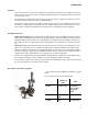
Engine and pump CHAPTER 2: ENGINE AND PUMP MTD log splitters are available with a variety of horizontal and vertical shaft engines. This manual covers procedures that are the same for all engine models available. Specific engine procedures are covered in the engine’s service manual. Horizontal shaft engines Thin headed wrench Spacer shield To remove/replace the engine: 1. Remove the three coupling support bracket nuts using a pair of 1/2” wrenches. See Figure 2.1.
2010 Log Splitters NOTE: If the engine is not being replaced, skip to step 10. 7. Remove the set screw in the engine coupling using a 1/8” hex key. See Figure 2.3. Set screw NOTE: When installing the engine coupling, apply a small amount of releasable thread locking compound such as Loctite® 242 (blue) to the set screw and tighten it to a torque of 78 in lbs (9 Nm) 8. Remove the engine coupling and key. NOTE: If the pump shows any signs of an impact, check the coupling support bracket.
Engine and pump Vertical shaft engines To remove/replace the engine: 1. Remove the three engine mounting screws using a 1/2” wrench. 2. Remove the engine from the log splitter. NOTE: If the engine is being replaced, continue to step 3. 3. Remove the set screw in the engine coupling using a 1/8” hex key. 4. Remove the engine coupling and key. Engine mounting screws Figure 2.5 To install a vertical shaft engine: Set screw 1. Install the spider in the pump coupler half. 2.
2010 Log Splitters Engine coupler gap MTD uses jaw type couplers to connect the engine to the pump. Jaw type couplers are made of three parts; two metallic coupler halves and a polymer spacer referred to as a spider. This type of coupling will isolate the engine vibration from the pump. It also compensates for minor pump mis-alignments. The coupler must have a gap of 0.010” to 0.060” (0.25 - 1.5 mm) between the two metal halves in order to isolate the pump from the engine vibrations. To set the gap: 1.
Engine and pump Pump removal/replacement To remove the pump: 1. Place a suitable container, large enough to hold all of the fluid in the reservoir under the pump. NOTE: On models with a vertical shaft engine, remove the engine by following the procedures described in the vertical shaft engine section of this chapter. Hose clamp 2. Loosen the hose clamp that secures the suction hose to the pump. See Figure 2.10. 3.
2010 Log Splitters Coupling support bracket 7. Remove the set screw that secures the pump coupling half using a 1/8” hex key. See Figure 2.13. 8. Remove the coupling and the key. 9. Remove the four nuts and bolts that attach the coupling support bracket to the pump using a pair of 1/2” wrenches. See Figure 2.13. 10. Install the pump by following the previous steps in reverse order. NOTE: DO NOT use teflon tape on any fitting on an MTD log splitter.
Hydrualic Diagnosis CHAPTER 3: HYDRAULIC DIAGNOSIS OVERVIEW The main components of the log splitter are all fairly expensive. Hip-shot diagnosis will result in wasted time and money for the dealer. Throwing wrong parts at a log splitter gets expensive fast. Troubleshooting is a process of developing and testing theories about the problem that caused the customer to bring the log splitter in for repair. To properly diagnose a problem with the hydraulic system of a log splitter; 1. 2. 3.
2010 Log Splitters Understanding the hydraulic flow It starts at the reservoir (tank). See Figure 3.2. • The tank acts as the axle of the log splitter. • Check the level of the hydraulic fluid, and add hydraulic fluid through the oil fill port. • The tank is vented by a passage drilled through the pipe plug. See Figure 3.2. Figure 3.2 • The outlet on the engine side of the tank feeds hydraulic fluid directly to the pump. See Figure 3.3.
Hydrualic Diagnosis Pressurized line to the control valve The pump draws fluid from the tank, and forces it under pressure to the control valve. See Figure 3.4. Pump • The pump is capable of producing 3,400 PSI (234 bar) at a pump speed of 3,500 RPM. • The pump is a two-stage pump. • There is no relief valve in the pump. • There is unloading or by-pass valve in the volume circuit. • The pump is direct-driven from the engine.
2010 Log Splitters The open-center control valve does four things: See Figure 3.6. 1. Regulate: It regulates fluid pressure. 2. • If the pressure exceeds a pre-set limit, the relief valve opens, returning fluid directly to the tank. • In any no-load condition, pressure should not exceed 300 PSI (20 BAR). Forward: It drives the ram toward the base plate. 3. • In the forward position, the control valve directs pressurized fluid through the hose to the port at the rear of the cylinder.
Hydrualic Diagnosis The Cylinder See Figure 3.7. Cylinder • Both ports of the cylinder are connected to the control valve. • When pressure is applied to the port at the base of the cylinder (through the flexible high-pressure hose), the ram extends. • When pressure is applied to the shaft end of the cylinder (through the trunnion), the ram retracts. • When pressure is applied to one port, fluid from the other port is forced back to the control valve by the movement of the piston in the cylinder bore.
10 Log Splitters Log splitter test procedures 1. Preparation Troubleshooting and diagnosing a hydraulic system is a process that should be performed in a specific order. This chapter is laid out in the order the tests should be performed to get the best results. NOTE: There is a hydraulic system testing work sheet at the end of this chapter. The work sheet is designed to assist in troubleshooting the hydraulic system.
Hydrualic Diagnosis C. Fluid not getting to the pump See Figure 3.11. • If fluid is not reaching the pump, the log splitter will not work • Continued running with a dry pump will destroy the pump. This is not warrantable damage. • To check the fluid supply to the pump: Pump Oil free flowing a. Place a drain pan under the pump. b. Disconnect the suction hose from the pump. c. Fluid should flow freely from it. • Watch the hose that feeds the pump while the ram is in motion.
2010 Log Splitters F. Inspect the tank vent: See Figure 3.13. • The tank vent is drilled through the pipe plug. • As the fluid moves from the tank to the cylinder, it draws air in. As fluid moves from the cylinder back to the tank, air is forced out of the tank. • If the tank cannot “breathe” through the vent, extending the ram will form a vacuum in the tank. • If the tank cannot “breathe” through the vent, retracting the ram will pressurize the tank.
Hydrualic Diagnosis 3,500 RPM H. Engine performance: See Figure 3.15. • The engine should be adjusted to run at 3,500 RPM + 100. Check it with a tachometer. • The engine must be in good state of tune: good spark plug, clean air filter, fresh fuel, clean carburetor, correct valve lash. • The engine must be in good mechanical condition: good compression. • If the engine speed is set correctly, but it slowsdown excessively under load, there is an engine performance issue.
2010 Log Splitters 2. Pump base-line test (ram stationary) A. Perform all of the procedures described in the preparation section of this chapter. B. With the engine running, record the engine RPMs on the worksheet at the end of this chapter. NOTE: Copies of the worksheet can be downloaded from the dealer service site or photo copied out of this book. C. Record the flow meter reading on the worksheet. See Figure 3.17. D. Record the pressure reading on the worksheet. Flow meter Figure 3.17 E.
Hydrualic Diagnosis F. Do NOT exceed 3,200 PSI (220 Bars). This test is performed upstream of the relief valve in the log splitter hydraulic system, rendering the relief valve ineffective during the test. Over-loading the system will damage the pump. 2,000 PSI 1.5 lpm Figure 3.19 Pump By-pass Settings Pump Slowly close the needle valve to build 2,000 PSI (220 Bars). See Figure 3.19. Tonnage By-pass Pressure + 100 PSI G. Record the engine RPMs on the worksheet. H.
2010 Log Splitters 4. Control valve test A. Turn off the engine. B. Relieve hydraulic pressure from the system by moving the lever on the control valve through it’s full range of travel. C. Remove the test gauges from between the pump and the control valve. D. Reinstall the original hydraulic hose that connected the pump to the control valve. E. Install the test gauges between the log splitter control valve and the extend port on the hydraulic cylinder. See Figure 3.20. e1.
Hydrualic Diagnosis Relief Valve Settings Valve part number Tonnage H. Relief valve setting + 100 PSI 718-04706 27 and 33 3400 PSI (234 bar) 718-04739 21 2700 PSI (186 bar) 718-04740 25 3200 PSI (221 bar) Extend the cylinder fully using the log splitter control valve. • As the ram reaches the end of its travel, pressure will build until the relief valve opens. • Record the maximum pressure reached on the worksheet.
2010 Log Splitters System drawings Control valve in Neutral +LJK SUHVVXUH &RQWURO YDOYH /RZ SUHVVXUH 1R PRYHPHQW )LOWHU &\OLQGHU 3XPS 5HVHUYRLU Figure 3.21 24 • The pump drives hydraulic fluid to the control valve.
Hydrualic Diagnosis Control valve in Extend (splitting) +LJK SUHVVXUH &RQWURO YDOYH /RZ SUHVVXUH 1R PRYHPHQW )LOWHU &\OLQGHU 3XPS 5HVHUYRLU Figure 3.22 • The pump drives hydraulic fluid to the control valve. • The spool in the control valve directs pressurized fluid to the base end of the cylinder. • The pressurized fluid forces the piston up the bore of the cylinder. • As the piston moves up the bore, it displaces fluid that is on the ram side of the piston.
2010 Log Splitters Control valve in Retract +LJK SUHVVXUH &RQWURO YDOYH /RZ SUHVVXUH 1R PRYHPHQW )LOWHU &\OLQGHU 3XPS 5HVHUYRLU Figure 3.23 26 • The pump drives hydraulic fluid to the control valve. • The spool in the control valve directs pressurized fluid to the ram end of the cylinder. • The pressurized fluid forces the piston down the bore of the cylinder. • As the piston moves down the bore, it displaces fluid that is on the base side of the piston.
Hydrualic Diagnosis Relief in Neutral +LJK SUHVVXUH &RQWURO YDOYH /RZ SUHVVXUH 1R PRYHPHQW )LOWHU &\OLQGHU 3XPS 5HVHUYRLU Figure 3.24 • This drawing shows the relief valve in action with the control valve in neutral. • The relief action is the same no matter what position the control valve is in. • If pressure builds beyond the pre-set limit, the relief valve opens, spilling fluid through a port that returns it to the reservoir.
2010 Log Splitters 28
LOG SPLITTER HYDRAULIC SYSTEM WORK SHEET For use with test kit part number 759-3742 NOTE: This worksheet must be completed and submitted with the failed component for a warranty claim to be paid Model number NOTE: Detailed hydraulic system testing instructions can Serial number be found in the 2010 and Newer Log Splitters manPump number ual, form number 769-06184. 1.
3b. Continue closing the needle valve until the pressure gauge reads 2,000 PSI. Record the following: Pressure Mode Flow Capacities Tonnage GPM/LPM + 0.5 GPM 718-04127 21,25 and 27 1.5 (5.6 lpm) 718-04729 27 ton HP pump 3 (11 lpm) 718-04128 33 3 (11 lpm) Pump Engine RPM Flow meter reading Pressure reading Flow from the pressure mode flow capacities chart. • Open the needle valve to relieve the pressure and turn off the engine Interpreting the results: • 4.
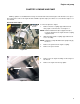
Control valve CHAPTER 4: CONTROL VALVE MTD uses three different control valves on log splitters. The size of the log splitter determines which valve is used. The three different valves are identical on the outside. Whenever testing or replacing a control valve, verify the part number of the valve on the splitter is the one listed in the parts drawing for that specific splitter. The valve part number is stamped into the end cap of the valve. See Figure 4.1.
2010 Log Splitters 6. Disconnect the high pressure hose from the pump. 7. Disconnect the high pressure supply hose from the valve using a 15/16” wrench. See Figure 4.3. 8. Disconnect the high pressure hose that connects the valve to the base of the cylinder. Hose to the cylinder Control valve high pressure supply hose Figure 4.3 Return hose fitting 9. Remove the return hose fitting: 9a. Hold the fitting with a 1” wrench. See Figure 4.4. 9b. Back off the jam nut with a 1” wrench. 9c.
Control valve 12. Hold the straight fitting with a 1” wrench. See Figure 4.6. Jam nut 13. Back off the jam nut using a 7/8” wrench. See Figure 4.6. 14. Unthread the straight fitting and valve from the cylinder. Straight fitting Figure 4.6 Elbow fitting 15. Place the control valve in a vise with the straight fitting facing up. See Figure 4.7. 16. Remove the straight fitting. 17. Mark the orientation of the elbow to the valve. 18. Loosen the jam nut on the elbow fitting using a 15/16” wrench. Figure 4.
2010 Log Splitters To install the valve: 19. Transfer the elbows orientation mark to the new valve. 20. Check or replace the O-rings on the fittings. 21. Thread the elbow into the valve, hand tight, until it is aligned with the orientation mark. 22. Tighten the jam nut until the O-ring is compressed. 23. Thread the end of the straight fitting without the jam nut into the control valve. Tighten the fitting until it compresses the O-ring. 24.
Control valve To replace the valve spring cover: NOTE: The spring cover part number is 718-0522. 1. Thoroughly clean the valve and surrounding area. NOTE: Any dirt or debris that gets inside the valve can destroy it. 2. Remove both of the socket headed cap screws that hold the spring cover to the valve using a 5 mm hex key. See Figure 4.9. 3. Remove the spring cover. 4. Carefully remove the old sealant from the valve. socket headed cap screw Figure 4.
2010 Log Splitters Control valve lever bracket To replace the lever bracket: NOTE: The lever bracket part number is 718-04765. 1. Thoroughly clean the valve and surrounding area. NOTE: Any dirt or debris that gets inside the valve can destroy it. 2. Remove the bowtie clip and the clevis pin. See Figure 4.11. 3. Slide the control lever out of the end of the spool and let it hang down. Bowtie clip Figure 4.11 4. Remove the master link locking clip. See Figure 4.12. 5.
CYLINDER CHAPTER 5: CYLINDER Cylinder removal To remove/replace the cylinder: 1. With the engine turned-off, relieve hydraulic pressure from the system by moving the lever on the control valve through it’s full range of travel. Hydraulic fluid under high pressure can be dangerous. A high-pressure hydraulic fluid leak or spray can penetrate the skin. If this happens, seek immediate medical attention to reduce the risk of blood poisoning leading to death or limb amputation. low pressure return line 2.
2010 Log Splitters 6. Remove the six screws that secure the log dislodger to the beam using a 9/16” wrench. See Figure 5.3. Log dislodger Figure 5.3 7. Remove the nut and bolt that attach the wedge to the cylinder ram using a pair of 3/4” wrenches. 8. Remove the cylinder from the log splitter. 9. Install the cylinder by following the previous steps in reverse order.
CYLINDER Cylinder rebuilding The cylinder used on the MTD log splitter come from two different suppliers but have the same part number. When replacing the whole cylinder, the two are interchangeable. However, when rebuilding the cylinder, the manufacturer (type) of the cylinder must be identified so that the proper rebuild kit can be ordered. The cylinders are identified as E-type and X-type.
2010 Log Splitters To rebuild a cylinder: The procedures to rebuild an “E-type” or an “X-type” cylinder are the same. Hot hydraulic fluid can cause burns. Do not work on the cylinder until the hydraulic system has cooled to ambient temperature after use. Hydraulic fluid under high pressure can be dangerous. A high-pressure hydraulic fluid leak or spray can penetrate the skin. If this happens, seek immediate medical attention to reduce the risk of blood poisoning leading to death or limb amputation.
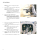
CYLINDER Ratchet strap 9. Wrap a ratchet strap around the wedge and the base plate. See Figure 5.9. 10. Hold the control valve in the extend position. NOTE: A bungee cord can be used to hold the control valve in the extend position. See Figure 5.9. Bungee cord 11. Tighten the ratchet strap until the ram is fully extended. Figure 5.9 12. Move the control valve to the retract position. 13. Wrap a heavy duty ratchet strap around the cylinder and wedge. See Figure 5.10. 14.
2010 Log Splitters 17. Remove the nut and bolt that attached the wedge to the cylinder ram using a pair of 3/4” wrenches. See Figure 5.12. Wedge bolt Figure 5.12 Rod guide 18. Place the cylinder in a vise with padded jaws. NOTE: DO NOT over tighten the vise. This can deform the cylinder preventing the piston and rod removal. 19. Remove the two screws and washers that hold the rod guide in place. See Figure 5.13. NOTE: There is thread locking compound on the screws.
CYLINDER 22. Clean the paint from the inside edge of the cylinder. See Figure 5.15. NOTE: Paint on the inside edge of the cylinder can catch the back-up ring, pulling it out of the grove and wedging between the rod guide and the cylinder wall. 23. Pull the ram out of the cylinder. Clean paint from the inside edge of the cylinder Do not use compressed air to force the piston out of the log splitter bore. Compressed air may eject the piston with dangerous force.
2010 Log Splitters 28. Carefully pry the outer piston seal off of the piston. See Figure 5.17. 29. Carefully pry the O-ring out of the groove in the piston. 30. Install a new O-ring and outer piston seal. Outer seal O-ring Figure 5.17 31. Carefully pry the back-up ring out of the groove in the outside diameter of the rod guide. 32. Carefully pry the O-ring seal out of the groove in the outside diameter of the rod guide. See Figure 5.18. Back-up ring O-ring Figure 5.18 Internal seal 33.
CYLINDER Back-up ring 37. Install a new back-up ring in the groove, positioned at the edge of the groove that is closer to the side of the rod guide that has the screw holes. 38. Install a new O-ring seal in the groove, next to the back-up ring. O-ring Figure 5.20 39. Lubricate the piston with the same type of fluid that will be used in the hydraulic system of the log splitter: 10W hydraulic fluid, or Dexron III automatic transmission fluid. 40.
2010 Log Splitters 48. Tighten the screws and washers to lock the rod guide in place. See Figure 5.22. 49. Put the cylinder in its normal operating position. 50. Attach the wedge to the ram. 51. Attach the log dislodger. 52. Install the control valve. 53. Connect the hydraulic lines. NOTE: When tightening hoses with O-ring face fittings, hold the hose so that the center part of it does not rotate against the O-ring while the swivel section is tightened.
Wedge and Beam CHAPTER 6: WEDGE AND BEAM Wedge Starting with 2010 production, MTD log splitters have a new beam design. The new beam is made from a heavy gauge U-channel with a flat plate welded to the top. This replaces the old extruded I-beam design. The new beam is machined to tighter tolerances then the old design, eliminating the need for an adjustable gib. Bolt should rotate freely when properly installed To replace a wedge: 1. Extend the wedge to the middle of the beam. 2.
2010 Log Splitters Beam To remove/replace the beam: 1. With the engine turned-off, relieve hydraulic pressure from the system by moving the lever on the control valve through it’s full range of travel. NOTE: If the shop has equipment that can safely lift the cylinder without straining the hydraulic lines, this job can be done without disconnecting the hoses. Hydraulic fluid under high pressure can be dangerous. A high-pressure hydraulic fluid leak or spray can penetrate the skin.
Wedge and Beam 8. Remove the six screws that attach the log dislodger to the beam using a 9/16” wrench. See Figure 6.5. NOTE: The 33 ton models only have four screws. 9. Dislodger Remove the dislodger from the log splitter. Figure 6.5 10. Remove the six nuts and bolts that attach the wedge retainer plates to the wedge using a pair of 3/4” wrenches. See Figure 6.6. Retainer plate bolts Figure 6.
2010 Log Splitters 12. Remove the log trays by removing screws that attach them to the beam using a 1/2” wrench. See Figure 6.8. Log tray Figure 6.8 13. Pull on the locking pin and rotate it until it stays in the unlocked position. 14. Move the beam to the vertical position. Pivot pin The beam weighs around 150 lbs. Take measures to prevent the beam from falling on the technician while separating it from the tank. ! CAUTION 15. Remove the cotter pin from the pivot pin. See Figure 6.9. 16.
Tank and Tires CHAPTER 7: TANK AND TIRES Tank To remove/replace the tank: 1. With the engine turned-off, relieve hydraulic pressure from the system by moving the lever on the control valve through it’s full range of travel. Hydraulic fluid under high pressure can be dangerous. A highpressure hydraulic fluid leak or spray can penetrate the skin. If this happens, seek immediate medical attention to reduce the risk of blood poisoning, which can lead to death or limb amputation. Drain pan 2.
2010 Log Splitters Return hose 7. Disconnect the return hose from the oil filter housing. See Figure 7.3. 8. Remove the oil filter housing by following the steps described in the oil filter housing section of this chapter. Figure 7.3 9. Pull on the horizontal locking rod. NOTE: Some models have a horizontal locking rod that can be rotated it until stays in the unlocked position. 10. Pivot pin Move the beam to the vertical position. The beam weighs around 150 lbs.
Tank and Tires 14. Remove the wheel assemblies by following the procedures described in the wheel assembly section of this chapter. 15. Remove the fenders by following the procedures described in the fender section of this chapter. Tongue 16. Remove the two nuts and bolt that hold the tongue to the tank using a pair of 9/16” wrenches. See Figure 7.5. 17. Slide the tongue out of the tank. 18.
2010 Log Splitters Wheel assembly To remove/replace the wheel assembly: NOTE: The wheel bearings are covered in Chapter 8: Maintenance. 1. Lift and safely support the rear of the log splitter. 2. Pry off the dust cap. See Figure 7.6. Dust cap Figure 7.6 3. Remove and discard the cotter pin. See Figure 7.7. 4. Remove the wheel castle nut using a 1 1/8” wrench. 5. Remove the washer. 6. Slide the wheel assembly and bearings off of the spindle. Cotter pin Figure 7.
Tank and Tires Fenders There are a variety of fenders available for MTD log splitters. They can be broken down to two types of fenders; plastic or metal. Plastic fenders To remove/replace a plastic fender: Fender support bracket 1. Remove the wheel by following the procedures described in the wheel assembly section of this chapter. 2. Remove the screw that passes through the fender support bracket and fender, threading into the tank. See Figure 7.9. 3.
2010 Log Splitters Metal fender To remove/replace a metal fender: 1. Remove the wheel by following the procedures described in the wheel assembly section of this chapter. 2. Remove both of the screws that hold the fender to the tank using a 1/2” wrench. See Figure 7.11. 3. Install the fender by following the previous steps in reverse order. Screws NOTE: The left and the right fenders have the same part number.
Tank and Tires Oil filter housing To remove/replace the oil filter housing: 1. With the engine turned-off, relieve hydraulic pressure from the system by moving the lever on the control valve through it’s full range of travel. Hydraulic fluid under high pressure can be dangerous. A highpressure hydraulic fluid leak or spray can penetrate the skin. If this happens, seek immediate medical attention to reduce the risk of blood poisoning, which can lead to death or limb amputation. Drain pan 2.
2010 Log Splitters 2. Thread the oil filter housing onto the tank nipple. NOTE: There is an arrow cast into the oil filter housing. The arrow must be pointing to the tank. See Figure 7.15. NOTE: A little bit of paint was rubbed on the housing to make the arrow more visible in the photo. Arrow Figure 7.15 3. Thread the return line fitting into the oil filter housing hand tight. 4. Align the nipple on the fitting so that it is pointing to the front of the splitter at a 30° from the beam. See Figure 7.
Tank and Tires Vertical locking rod To remove the vertical locking rod: Push cap 1. Pry the push cap off of the vertical locking rod. See Figure 7.17. 2. Remove the spring. 3. Slide the locking rod out of the uprights on the tank. Spring Figure 7.17 To install the vertical locking rod: Locking pliers 4. Slide the locking rod through the uprights on the tank from the engine side. 5. Slide the spring over the straight end of the locking rod. 6.
2010 Log Splitters Horizontal locking rod To remove/replace the horizontal locking rod: 1. Move the beam to the vertical splitting position. 2. Dive out the roll pin using a 1/8” pin punch. See Figure 7.19. 3. Pull the locking rod out of the bracket, catching the spring when the rod is removed. Roll pin Figure 7.19 To install the horizontal locking rod: 4. Position the spring inside the lock rod bracket. 5.
Maintenance CHAPTER 8: MAINTENANCE Lubrication To help keep the MTD log splitter in proper running order, MTD recommends the following maintenance intervals be used (adjustable to local conditions). .
2010 Log Splitters Engine maintenance The recommended maintenance intervals listed in this manual are a guideline. They are adjustable for local conditions. Maintenance items Interval Oil Change* 25 hrs Replace the air filter 25 hrs Spark plugs 100 hrs Fuel filter 100 hrs Clean the engine 25 hours * First oil change at 5 hours. Please refer to the engine service manual for specific engine maintenance procedures. Clean the engine Air cooled engines cool better if they are clean.
Maintenance Engine oil Currently there are four engines available for the MTD log splitter. A generic oil change procedure will be described in this manual. For specific instructions, refer to the engine service manual. To change the oil: Drain plug 1. Clean around the base of the engine. 2. Place a suitable container under the engine to catch the oil. 3. Remove the drain plug. See Figure 8.1. 4. Remove the dip stick. 5. When the oil stops draining, install the drain plug. 6.
2010 Log Splitters Hydraulic oil The MTD log splitter has an open vent in the dip stick plug. This leave the hydraulic oil in the reservoir open to collect dirt and water from the atmosphere. Because of this, the hydraulic oil should be changed ever 100 hours. To change the hydraulic oil: NOTE: The oil filter should be changed at the same time the hydraulic oil is changed. 1.
Maintenance Wheel bearings The wheel bearing on the MTD log splitter will need to be serviced from time to time. The frequency of how often they need to be serviced depends on how the splitter is towed. A splitter that was towed home from the store and parked in the yard, never moving, will not need to have the bearings serviced as often as the splitter that gets towed from job site to job site.
2010 Log Splitters 5. Clean and inspect the bearing races. NOTE: If there are signs of wear or damage to a bearing race, it and its matching cone must be replaced. NOTE: To replace a race: 6. • Drive the old race out using a flat tipped punch. • Clean the old grease out of the wheel assembly. • Carefully drive in the new race(s) using a bearing race driver. See Figure 8.5. Clean and inspect the bearing cones.
MTD Products Inc - Product Training and Education Department FORM NUMBER - 769-06184 07/2010