Commercial Zero-Turn Riding Mower Professional Turf Equipment S6031 S7237 OPERATOR’S AND SERVICE MANUAL
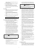
TABLE OF CONTENTS Foreword . . . . . . . . . . . . . . . . . . . . . . . . . . . . . . . . . . . . . . . . . . . . . . . . . . . . . . . . . . . . . . . . . . . . . . 3 General Safety Operations . . . . . . . . . . . . . . . . . . . . . . . . . . . . . . . . . . . . . . . . . . . . . . . . . . . . . . . . . 4 A.Danger . . . . . . . . . . . . . . . . . . . . . . . . . . . . . . . . . . . . . . . . . . . . . . . . . . . . . . . . . . . . . . . . . . 4 B. Warning. . . . . . . . . . . . . . . . . . . . . . . .
FOREWORD The Tank Hydrostatic Zero-Turn Synchro-Steer Commercial Riding Mower provides superb maneuverability, mid-mount cutting capability for professional landscapers, commercial lawn service companies, professional turf managers and golf course superintendents. The machine incorporates many safety features that should be studied by all operators and maintenance personnel before use. The list of safety precautions should receive particular attention.
GENERAL SAFETY OPERATIONS 7. 8. A. DANGER 1. 2. 3. 4. Do not operate machine in confined areas where exhaust gases can accumulate. Do not operate machine without mower chute deflector in place and operational. Do not carry passengers. Do not operate nor store machine in areas where open flames, electrical switches and circuit breakers are present. B. WARNING 1. Do not operate machines under the influence of alcohol or drugs. 2.
B. Related to Fuel in reverse order (I.E., the negative terminal of the weak battery first). Batteries should be re-charged at a constant voltage...generally 14.5 +/- 0.5 volts DC for a nominal 12 volt DC battery. 1. Fuel is highly flammable and its vapors can explode if ignited. Please respect it. 2. Do not smoke or permit others to smoke while handling fuel. 3. Always use approved containers for fuel and fill slowly to decrease the chance of static electricity buildup and spillage. 4.
switch if another person approaches while you are operating the mower. 15. Never attempt to operate the traction unit without the mowing deck attached. 16. Keep the mower and especially the engine and hydraulic components clean and free of grease, grass and leaves to reduce the chance of fire and to permit proper cooling. 4. DANGER: If ROPS and OPDs are folded down or missing, seat belts shall not be fastened. Worn or damaged seat belt assemblies must be replaced prior to operator use. 5.
2. 3. 4. incorporates a “ratchet” feature to allow the handle to be positioned as desired. See Figure 2 below. The seat bottom is covered with a heavy-duty vinyl fabric. An OPS in the form of a switch, is integrated into the seat bottom and is connected to the machine electrical system. The seat back is also covered with a heavy-duty vinyl fabric, it adjusts to recline up to 16 degrees, (lever actuated on operator’s left side).
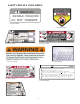
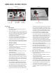
SAFETY DECALS AND LABELS WARNING SHIELD MISSING DO NOT OPERATE Part Number: 00030635 Part Number: 01002166 Part Number: 777S33087 Part Number: 777S30503 Part Number: 777D12837 Part Number: 02005110 ! WARNIN Maximum weight on hitch is 50 lbs. Maximum towed load is 500 lbs. Never allow passengers on towed equipment. Loss of traction can occur on slopes, 5 (9%) maxi Travel slowly and allow extra distance to stop. Use caution during turns to avoid jack-knifing.
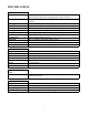
SPECIFICATIONS GENERAL INFO. Controls: Parking Brake: Seat: Frame: Instrumentation Front Wheels: Drive Wheels: Tire Pressure: Fuel Tank: Ground Speed: Net Weight: Engine ignition and start switch; throttle; choke; speed control pedals; electric blade clutch switch; parking brake; mower deck lift 14” diameter steering wheel coupled to hydraulic steering valve and cylinder Mechanical linkage brake to internal drum brakes Adjustable seat and armrests.
OPERATING INSTRUCTIONS Figure. 4 Engine throttle Choke Lever Figure. 5 Ignition Switch Electric Blade Clutch Switch Tach and Hour Meter Power Implement Lift A.General 1. When Mowing: Keep adults, children, and pets away from the area to be mowed. b. When operating this mower, in the forward direction, do not allow the speed control pedals to rapidly return to Neutral. Always operate the pedal smoothly and avoid any sudden movements when starting and stopping. c.
g. Slow-down before turning and come to a complete stop before any zero turn maneuver. h. Do not stop machine or park machine over combustible materials such as dry grass, leaves, debris, etc. 3. To Mow Grass and Produce a Striped Pattern a. Pick a point on the opposite side of the area to be mowed (post, tree, shrub, etc.). b. If on an hillside, start at the bottom so that the turns are uphill rather than downhill. c. Align the mower so as to head directly toward the object on the far side. d.
C.Initial Adjustments highest (also transport position) or lowest (also for mower deck removal and installation). 1. The following features are incorporated into the hydraulic actuated valve implement lift design: Lever implement lift allows for some operators with physical limitations to use the implement lift mechanisms and the machine; reduces potential for operator fatigue; accommodates a variety of operator sizes, shapes, and strengths. 7. Fuel Shutoff Valve: (See Figure 7.
D. Zero Turn Break-In And Operating Procedures of the deck on each side of the mower. (Four dimensions.) Note: The front edge of the mowing deck should be DANGER: 1/8"-1/4" below the rear edge of the deck so that the blades are cutting grass in only the front half of their circular path. This decreases friction and reduces the drive power required. c. Reread the “When Mowing” Safety Precautions. If the cut height is below 1-1/2” the pitch should not exceed 1/16”.
2. also referred to as blade control switch) is in the “off” (down) position. Move the choke control forward and the engine speed control (throttle) forward (half way). Note: E.F.I. Tanks do not have a choke control. 3. Insert the ignition key, turn the switch toward the spring-loaded “Start” position, maintain the Start position until the engine begins to run, then release the switch (it will return to the “Run” position). 4. Retard the choke slowly by moving it rearward.
c. d. e. f. g. Make sure that the speed control pedal is in the neutral position. Turn the electric blade clutch switch “Off”. Push the throttle control to a position a third of the way between slow and fast. Insert the key in the ignition and start switch and turn the switch to “On”. Gasoline Engine: If the engine is cold, push the choke to the on position. Note: E.F.I. Tanks do not have a choke control. h. Turn the ignition key in a clockwise direction to the “Start” position until the engine starts.
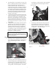
Height of Cut Clevis Pin Figure. 9 Linch Pins Linch Pins MAINTENANCE AND SERVICE Cover Plate WARNING: Spindle Disconnect the spark plug wires or remove the key from the ignition to prevent the engine from accidentally starting before performing any maintenance on this mower. A. Mower Deck 1. Removing the Mower Deck: Apply the parking brake. Remove ignition key and both spark plug caps. b. Lower the cutter deck to the ground. Place the height of cut clevis pin in the “lock” position. c.
g. To replace the blade reverse the above process and tighten nut to 100-120 lb ft. WARNING: Never mow with dull blades! Blades that are bent should be replaced! The cutting blades are sharp and can cause severe injury. Wrap the cutting surface of the blade with a rag to avoid injury. A dull blade requires more horsepower than one that is sharp. 3. Sharpening a Blade. Set the parking brake. Clean any debris from the blades. Keep blades sharp and free of build up at all times. c.
d. Raise the seat forward to expose the hydraulic oil fill point. e. Clean the area around the hydraulic fill oil cap. f. Remove hydraulic fill oil cap. g. Place a suitable container (at least 1 gallon) under the hydraulic reservoir and filter. h. Remove the hydraulic filter to allow hydraulic oil to drain. Remove the drain plug from the bottom of the hydraulic oil tank to drain. Replace the plug. i. Place a small pan under the pump motor frame.
Attach the end of the red jumper cable to the Positive terminal (+) of the charged battery. b. Attach the other end of the red jumper cable to the Positive terminal (+) of the low charge battery. c. Attach the end of the black jumper cable to the Negative terminal of the charged battery. d. Attach the other end of the black jumper cable to the frame of the unit with the low charge battery. 6.
b. c. Front Wheel—25 psi max; 20-25 psi recommended Cutting Deck Ball Wheels—Solid Polyurethane. Use the Following guidelines for maintaining the tires: a. b. 2. Balance inflation pressure between the rear tires to help maintain straight travel (see tire side wall for proper inflation pressure). Keep the valve caps tightened to prevent air pressure loss. Leaking Tires: When a flat tire occurs, repair or replace immediately. The normal procedure is to remove the wheel and replace it with a spare.
Note: After unit is up to operating temperature, turn off engine and re-check hydraulic oil. If oil appears foamy or contains excessive air bubbles, DO NOT OPERATE UNIT. Contact service technician. F. Hydraulic System WARNING: Never overfill the hydraulic units. Damage can occur if the oil level is not within the proper operating range. 3. Note: When adding hydraulic oil, do so in small quantities and recheck the oil level before adding more.
tative for the procedure to reset the RTN mechanism on the hydrostatic pumps. If the hydrostatic pump RTN is adjusted, the control linkage must also be readjusted. c. d. e. G. Storage 1. General: If your mower will not be in service for a few months, it should be stored in a dry location that is not subject to drastic changes in temperature. Do not store in areas where heaters, furnaces, or electrical appliances are present. Before storing, the following maintenance procedures should be performed.
MAINTENANCE SCHEDULE GT-2, GT-2.5, adjust to 0.012" - 0.015" Ogura GT-3, GT3.5, adjust to 0.015" - 0.022" E. Yearly Checks A. Daily Checks 1. 1. Before starting engine: a. Check the fuel level.** b. Check the engine oil level.** c. Check the hydraulic oil level. d. Check the hydraulic hoses for leaks, abrasion, kinks, twists, or a flattened condition. e. Check the tires and tire pressure. Drive Tires: 10-12 psi. Front Wheels: 20-25 psi. f.
. OIL CHART Apply a few drops of engine oil or use a spray lubricant. Apply the oil to both sides of pivot points. Wipe off any excess. Start engine and operate mower briefly to insure that oil spreads evenly.
Performance Adjustments B. Deck Corner Ball Wheel Roller Settings 1. A. Engine RPM Check and Adjustment Description High RPM Spec. Low RPM Spec. 31 & 37 Kawasaki 3600 +/-50 1550 +/-100 NOTE: RPM Specs. are for free running engines under no load. 1. 2. 3. 4. 5. 6. 7. 8. 9. Verify that the speed control pedals are in the neutral position, the parking brake is on, and the PTO drive is disengaged.
2. 3. 4. 5. 6. 7. 8. lower the mowing deck into the 4" height of cut position. (The 4" height of cut position is recommended in order for one to see and obtain a measurement. Any height of cut position is acceptable as long as a proper measurement can be taken.) Check the right and left front tire pressure. Adjust as necessary to 20-25 psi. Tire pressure can affect blade height by as much as a 1/4”. Check the right and left rear Drive tire pressure. Adjust as necessary to 10-12 psi.
WIRING DIAGRAM GD: 02002824 27
Stems (Dandelion, Bahia, Buckhorn, etc.
SLOPE GAUGE DO NE , RE PRE S E NTIN G A 15 °S LOP E OR A FENCE POST A CORNER OF A BUILDING A POWER POLE SIGHT AND HOLD THIS LEVEL WITH A VERTICAL TREE USE THIS PAGE AS A GUIDE TO DETERMINE SLOPES WHERE YOU MAY NOT OPERATE SAFELY. FOL ND O T TED LI 20° WARNING Do not mow on inclines with a slope in excess of 20 degrees (a rise of approximately 3 feet every 10 feet). A riding mower could overturn and cause serious injury.
CALIFORNIA EMISSION CONTROL WARRANTY STATEMENT YOUR WARRANTY RIGHTS AND OBLIGATIONS The California Air Resources Board and MTD Consumer Group Inc are pleased to explain the evaporative emission control system warranty on your 2008 lawn mower. In California, new lawn mowers must be designed, built and equipped to meet the State’s stringent anti-smog standards.
WARRANTED PARTS: The repair or replacement of any warranted part otherwise eligible for warranty coverage may be excluded from such warranty coverage if MTD Consumer Group Inc demonstrates that the lawn mower has been abused, neglected, or improperly maintained, and that such abuse, neglect, or improper maintenance was the direct cause of the need for repair or replacement of the part.
MANUFACTURER’S LIMITED WARRANTY FOR CUB CADET COMMERCIAL TANK ZERO-TURN COMMERCIAL RIDING MOWER IMPORTANT: To obtain warranty coverage owner may be required present proof of purchase and applicable maintenance records to the servicing dealer. Please see the operator’s manual for information on required maintenance and service intervals. In addition, Cub Cadet may deny warranty coverage if the hour meter, or any part thereof, is altered, modified, disconnected or otherwise tampered with.