TANK - S STEERING SYSTEM ADJUSTMENTS Model Year 2009
TANK - S STEERING SYSTEM ADJUSTMENTS. TABLE OF CONTENTS: PAGE 2 ) ……………………………….. System Overview. PAGE 3 ) ……………………………….. System & Adjustment Terminology. Neutral Setting. Steering Synchronization. Front Wheel Toe. Front Wheel Tracking. Speed Setting. Return to Neutral & Speed Setting. Parking Brake Neutral Lockout. Diagnostics. Steering Not Responsive or Jerky Return to Neutral Checks. PAGE 4 ) ………………………………… Diagnostics. cont. Steering Synchronization Checks. Adjustment & Calibration Procedures.
SYSTEM & ADJUSTMENT TERMINOLOGY: Neutral Setting: With the brake off, the unit should not creep forward or reverse w/o applying the directional control pedals. The drive pumps and linkage have an adjustable return to neutral setting built in. Steering Synchronization: When a turn is negotiated, the individual rear drive wheel speed must be synchronized, or coordinated with the steer angle of the front wheels.
DIAGNOSTICS: cont. Steering Synchronization Checks: Drive unit on a flat level surface at about ¼ speed. Gradually turn to the left. Observe the rotation of the inside (LH) rear drive wheel. It should rotate slower than the RH drive wheel. When the LH front wheel is perpendicular ( 90 deg.) to the center line or main frame of the unit, the inside (LH) rear drive should stop turning. Continue the LH turn. When the maximum turn is achieved, the inside (LH) rear drive wheel should rotate in reverse.
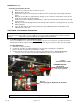
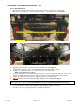
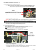
ADJUSTMENT & CALABRATION PROCEDURES: cont. Tracking Adjustment: cont. e. Mount 2 magnetically mounted laser line torpedo levels to the outside of each steering yoke pointing toward the rear tires. Or, use a long straight edge along the outside of the yoke to the rear tire. f. Using the rear tire treads as reference, the laser line or straight edge point location should match the same location on the RH rear as the LH rear tread. See Fig # 3.
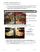
ADJUSTMENT & CALABRATION PROCEDURES: cont. Toe In / Out Adjustment: a. Measure the center line of the front tire tread to the center line of the other front tire tread. Measure to a point approx. 7-1/2” from ground surface. Record dimension. See Fig. # 5. 7 ½” Fig. # 5. Measurement Centerline Front. Fig. # 6. Measurement Centerline Rear. b. c. d. e. f. g. Repeat procedure at the rear of the tires. Record dimension. See Fig. # 6. The dimension should be 1/8” to 1/4” less across the front than the rear.
ADJUSTMENT & CALABRATION PROCEDURES: cont. WARNING: Before making any adjustments, shut engine off and allow it to cool. When running the engine is not necessary to perform procedures, remove ignition key, disconnect both spark plug wires and disconnect the battery. Refer to the Operators’ Manual for complete Safety Instructions. # 2. Steering Synchronization & Neutral Setting: These two adjustments can be made simultaneously.
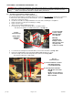
ADJUSTMENT & CALABRATION PROCEDURES: cont. # 2. Steering Synchronization & Neutral Setting: cont. j. k. Insert a 5/16” pin, dowel or bolt through the steering toggle alignment holes. See Fig.1 & Fig. 2, Page 4. If the pin / holes do not line up, manually readjust the position of the LH front wheel. Insert 5/16” pins, dowels or bolts through the alignment holes in the Pump Control Arm. See Fig. # 9a. The pins must pass easily through all 4 plates of each alignment hole.
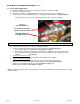
ADJUSTMENT & CALABRATION PROCEDURES: cont. # 2. Steering Synchronization & Neutral Setting: cont s. Adjust the Control Pedal Neutral by loosening the bolt securing and aligning the spring for the pedal RTN. The component is secured through a slotted hole. Loosening the bolt will allow the neutral spring mechanism to align itself in relation to the linkage neutral position. See Fig. # 11. Fig. # 11. Control Pedal - Return to Neutral Spring Must Be Centered in Relation to Linkage Bolt. Alignment Bolt.
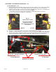
ADJUSTMENT & CALABRATION PROCEDURES: cont. # 4. Forward Speed Adjustment: The maximum FWD ground speed can be adjusted from approx. 11 MPH to 8 MPH. a. Park unit on a flat level surface. b. Position the front wheels straight toward the front of the unit as if driving in a straight line. c. Insert a 5/16” pin, dowel or bolt through the steering toggle alignment holes. See Fig.# 2 Page 4. If the pin / holes do not line up, manually readjust the position of the LH front wheel. Fig. # 13. Speed Adjustment.
NOTES