Safe Operation Practices • Set-Up • Operation • Maintenance • Service • Troubleshooting • Warranty Operator’s Manual Tank M60-KW WARNING READ AND FOLLOW ALL SAFETY RULES AND INSTRUCTIONS IN THIS MANUAL BEFORE ATTEMPTING TO OPERATE THIS MACHINE. FAILURE TO COMPLY WITH THESE INSTRUCTIONS MAY RESULT IN PERSONAL INJURY. CUB CADET LLC, P.O. BOX 361131 CLEVELAND, OHIO 44136-0019 Printed In USA Form No.
1 To The Owner Thank You Thank you for purchasing a Cub Cadet Commercial Zero-Turn tractor. It was carefully engineered to provide excellent performance when properly operated and maintained. Please read this entire manual prior to operating the equipment. It instructs you how to safely and easily set up, operate and maintain your machine. Please be sure that you, and any other persons who will operate the machine, carefully follow the recommended safety practices at all times.
Important Safe Operation Practices 2 WARNING! This symbol points out important safety instructions which, if not followed, could endanger the personal safety and/or property of yourself and others. Read and follow all instructions in this manual before attempting to operate this machine. Failure to comply with these instructions may result in personal injury. When you see this symbol.
15. Mow only in daylight or good artificial light. 16. Never carry passengers. 17. Back up slowly. Always look down and behind before and while backing to avoid a back-over accident. Be aware and pay attention to the safety system function that stops power to the blades when driving in reverse. If not fuctioning properly, contact an authorized dealer for safety system inspection and repair. 18. Slow down before turning. Operate the machine smoothly. Avoid erratic operation and excessive speed. 19.
. Do not mow on wet grass. Reduced traction could cause sliding. 3. If ramps are used, they must be full width, and secured to the trailer or truck. 6. Do not tow heavy pull behind attachments (e.g. loaded dump cart, lawn roller, etc.) on slopes greater than 5 degrees. When going down hill, the extra weight tends to push the tractor and may cause you to loose control (e.g. tractor may speed up, braking and steering ability are reduced, attachment may jack-knife and cause tractor to overturn). 4.
could come in contact with the ROPS and OPDs. Contact of ROPS and OPDs by items such as tree limbs, clothes lines, guy wires, and buildings, could create hazardous conditions whereby the machine could experience a tipover or roll-over. The canopy can provide protection for the operator from some environmental exposure (sunlight, rain, etc.). Work lights may be available. 6. 7. • Hydraulic controls are actuated to release pressure on pumps, cylinders, etc.
m. Never operate/store the machine or fuel container inside where there is an open flame, spark or pilot light as on a water heater, space heater, furnace, clothes dryer or other gas appliances. Do not change the engine governor settings or over-speed the engine. The governor controls the maximum safe operating speed of the engine. 13. n. Allow a machine to cool at least five minutes before storing. Maintain or replace safety and instruction labels, as necessary. 14. o.
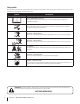
Safety Symbols This page depicts and describes safety symbols that may appear on this product. Read, understand, and follow all instructions on the machine before attempting to assemble and operate. Symbol Description READ THE OPERATOR’S MANUAL(S) Read, understand, and follow all instructions in the manual(s) before attempting to assemble and operate WARNING— ROTATING BLADES Do not put hands or feet near rotating parts or under the cutting deck. Contact with the blade(s) can amputate hands and feet.
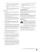
or a corner of a building... e) a 1 5 ° slop or a fence post nts ine ( r e p r ese dl on g d o tte l Fold a Sight and hold this level with a vertical tree... 15° Use this page as a guide to determine slopes where you may not operate safely. WARNING! Do not operate your lawn mower on such slopes. Do not mow on inclines with a slope in excess of 15 degrees (a rise of approximately 2-1/2 feet every 10 feet). A riding mower could overturn and cause serious injury.
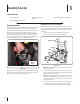
3 Assembly & Set-Up Contents of Crate • One Lawn Tractor • • One Engine Operator’s Manual • One Tractor Operator’s Manual One Deck Wash Hose Coupler Tractor Preparation Install Roll Over Protective System (ROPS) Remove the upper crating material from the shipping pallet, and cut any bands or tie straps securing the tractor to the pallet. The Roll Over Protective System (ROPS) has not been installed on your unit for shipping purposes.
4. Install the upper ROPS section onto the lower ROPS “posts”. Install the (1⁄2-13 x 3.25) HHCS bolts, nuts and washers. See Fig. 3-3. 8. Move the upper ROPS section to the upright position, and insert the locking pins with their retainer hairpin clips. See Fig. 3-5. Hex Bolts Washers Hairpin Clips Locking Pin Nuts Lower ROPS Posts Figure 3-3 5. Tighten Upper ROPS section bolts after both RH & LH hardware is installed. 6. Tighten the frame mounting hardware to 80-90 lb.-ft. torque. See Fig. 3-2.
Adjusting Drive Control Levers To adjust the front-to-rear angle of the control levers: The RH and LH drive control levers can be adjusted up or down and fore-and-aft for the comfort of the operator. Proper drive control lever and seat adjustment will result in the following: 1. Loosen the nuts on the control lever mounting bolts, leaving the bottom one fairly snug. The top hole is slotted, allowing the control lever to pivot on the bottom bolt.
Connecting the Battery Cables California Proposition 65 Warning! Battery posts, terminals, and related accessories contain lead and lead compounds, chemicals known to the State of California to cause cancer and reproductive harm. Wash hands after handling. Caution! When attaching battery cables, always connect the POSITIVE (Red) wire to its terminal first, followed by the NEGATIVE (Black) wire.
4 Controls & Features ROPS (Roll Over Protective System) START Parking Brake RH Drive Control Lever LH Drive Control Lever SLOW FAST START RUN CHOKE OFF CHOKE ON ON Ignition Switch Throttle Control PARK BRAKE Fuel Tank Cap POSITION OFF FORWARD “N” NEUTRAL Cup Holder Lever START PTO Switch G REVERSE Digital Tachometer & Hour Meter Choke WARNIN Fuel Shut-Off Valve Deck Height Index Deck Lift Pedal Figure 4-1 NOTE: References to LEFT, RIGHT, FRONT, and REAR indicate that Deck L
Ignition Switch The ignition switch is located on the RH console to the right of the operator’s seat. The ignition switch has three positions as follows: OFF - The engine and electrical system is turned off. Throttle Control OFF RUN START RUN - The tractor electrical system is energized. START - The starter motor will turn over the engine.
Fuel Shut-Off Valve Transmission Bypass Valves (Not Shown) The fuel shut-off valve is located on top of the fuel tank(s). When turned in a clockwise direction until it stops, it will shut off the flow of fuel to the engine. When turned in a counterclockwise direction it will open and allow fuel to flow to the engine. See Fig. 4-2. The transmission bypass valves (one for each the RH and LH transmission) are located just in front of the engine and just behind the seat.
5 Operation General Safety • RECEIVE INSTRUCTION — Entirely read this operator’s manual. Learn to operate this machine SAFELY. Do not risk INJURY or DEATH. Allow only those who have become competent in its usage to operate this tractor. • Before starting the engine or beginning operation, be familiar with the controls. The operator should be in the operator’s seat.
3. Engage the parking brake. 4. Make certain the PTO switch is in the disengaged (down) position. Check if deck is level. When correctly adjusted the mower deck should be level side to side, and the front of the deck should be approximately 1⁄4” lower than the rear of deck. If deck needs to be leveled, refer to the Maintenance & Adjustments section. 5. Push the choke lever to the on position. 6. Push the throttle control forward about halfway. 9.
Stopping the Engine 1. Place the PTO switch in the “OFF” position. 2. Move the RH and LH drive control levers fully outward in the neutral position. 3. Engage the parking brake. 4. Move the throttle control to midway between the SLOW and FAST positions. 5. Turn the ignition key to the “OFF” position and remove the key from the ignition switch. 3. Move the RH and LH drive control levers inward in the neutral position. Refer to Figure 5-2.
1. Driving the Tractor Forward Warning! Keep all movement of the drive control levers slow and smooth. Abrupt movement of the control levers can affect the stability of the tractor and could cause the tractor to flip over, which may result in serious injury or death to the operator. 1. To turn to the left, move the left drive control lever rearward of the right lever. See Fig. 5-4. Forward Left Turn Slowly and evenly move both drive control levers forward. The tractor will start to move forward.
Driving the Tractor In Reverse Turning While Driving Rearward WARNING! Always look behind and down on both sides of the tractor before backing up. Always look behind while traveling in the reverse direction. To turn the tractor while driving rearward, move the control levers as necessary so that one lever is forward of the other. The tractor will turn in the direction of the forward control lever. 1. 1. Slowly and evenly move both drive control levers rearward.
Executing a Zero Turn Stopping the Tractor Warning! When executing a zero turn, the tractor MUST BE STOPPED. Executing a zero turn while the tractor is moving can significantly reduce your control of the tractor and will cause severe turf defacement to occur. 1. Stop the forward or reverse motion of the tractor by moving the two drive control levers to neutral. 2. To turn clockwise, move the left control lever forward while simultaneously moving the right control lever rearward. See Fig. 5-9. 1.
Using the Mower Deck Warning! Make certain the area to be mowed is free of debris, sticks, stones, wire or other objects that can be thrown by the rotating blades. NOTE: Do not engage the mower deck when lowered in grass. Premature wear and possible failure of the ‘V” belt and PTO clutch will result. Fully raise the deck or move to a non grassy area before engaging the mower deck. 1. Mow across slopes, not up and down. If mowing a slope, start at bottom and work upward to ensure turns are made uphill. 2.
Reconfigurable Mower Standard set-up Stems (Dandelion, Bahia, Buckhorn, etc.
6 Maintenance & Adjustments Maintenance Schedule Before Each use Check Engine Oil/ Gasoline Level Check Hydraulic Hoses For Leaks Check Tires & Tire Pressure Check Deck, Mower And Hydro Drive Belts Check Blades And Blade Bolt Tightness Check Safety Switches For Proper Operation Check Fluid Level In Transaxle Expansion Reservoir Every 25 Hours Every 50 Hours Every 100 Hours Every 500 Hours P P P Clean Mower P Lubricate Wear Points (See Chart) Grease Three Spindle Bearings Replace Air Filter * Chang
OIL CHART Apply a few drops of SAE engine oil, grease, or use a spray lubricant. Apply the oil to both sides of pivot points. Wipe off any excess. Start engine and operate mower briefly to insure that oil spreads evenly.
LUBRICATION CHART Use a grease-gun filled with NO. 2 Multipurpose Lithium Base Grease Number of Grease Fittings Description EVERY 25 HOURS 3 Blade Spindle Bearings WEEKLY 2 Front Caster Wheels 2 Front Caster Wheel Spindles 2 Mower Deck Ball Wheels Number of Grease Points Description WEEKLY 4 Mowing Deck Pivots 2 Deck Take-Up Idler Pivots 1 Axle Pivot 2 Steering Lever Pivots 1 Hydro Take-up Idler Pivot 1 Park Brake Pivot Spindle Lubricant: Use only Shell Alvania RL 2 grease.
Maintenance 3. Warning! Before performing any maintenance or repairs, disengage the PTO, move the drive control levers fully outward in the neutral position, engage the parking brake, stop the engine and remove the key to prevent unintended starting. Clean the area around the Hydraulic Oil fill neck. See Fig. 6-1. Hydraulic Oil Fill Cap Engine Refer to the Kawasaki Owner’s Manual for all engine maintenance intervals, procedures, specifications and instructions.
8. Place a small pan under the pump motor frame. Remove fill oil cap from hydraulic reservoir for faster drainage. Remove nut caps and drain oil from both left and right pumps. Replace and retighten nuts. See Fig. 6-2. 4. Fill the replacement filter with a good grade of 15W-40 oil and lubricate the sealing surface. 5. Screw the filter onto the filter base until it seats and then another one-half turn to seal.
• As a further precaution, only charge the battery in a well ventilated area. b. Loosen and remove the lug nuts and remove the wheel. • Always shield eyes and protect skin and clothing when working near batteries. c. • Batteries contain sulfuric acid and may emit explosive gases. Use extreme caution when handling batteries. Keep batteries out of the reach of children. Mount a wheel and tire, replace the lug nuts, and using a torque wrench, tighten them to 60 ± 10 ft-lbs. 2.
3. Pull back the lock collar of the nozzle adapter and push the adapter onto one of the deck wash nozzles at either end of the mower deck. Release the lock collar to lock the adapter on the nozzle. See Fig. 6-3. Pull Lock Collar Back Using the Transmission Bypass Valves If for any reason the tractor will not drive or you wish to move the tractor, the two hydrostatic transmissions are equipped with a bypass valve that will allow you to manually move the tractor short distances.
Battery Storage c. 1. When storing the tractor for extended periods, disconnect the negative battery cable. It is not necessary to remove the battery. 2. All batteries discharge during storage. Keep the exterior of the battery clean, especially the top. A dirty battery will discharge more rapidly. 3. The battery must be stored with a full charge. A discharged battery can freeze sooner than a charged battery. A fully charged battery will store longer in cold temperatures than hot.
6. Start the engine and allow to idle for a few minutes to ensure engine is operating properly. 7. Drive the tractor without a load to make certain all the tractor systems are functioning properly. 5. The right front blade tip height is fixed so you must adjust the left front tip to match it. See Fig. 6-5. Left Front of the Deck Adjustments Adjusting the Seat Refer to the Assembly & Set-Up section for instructions on adjusting the seat.
3. Start at the rear right to raise the rear of the deck, tighten the rear outer jam nut to raise the deck or loosen the rear outer jam nut to lower the rear of the deck. 4. Adjust the rear jam nut at the rear left to take the “slack” out of the threaded rod. 5. Tighten both inner jam nuts to secure the deck adjustment. 6. The final adjustment would be to take the “slack” out of the left rear linkage if the rear of the deck was raised by adjusting the jam nuts on the eyebolt.
Adjusting the Front Skirt Removing/Installing the Inner Baffle The front skirt can be raised or lowered depending on the mowing conditions. The skirt has three settings; low, medium and high. See the table on page 23 in the Operation section for more information. Raise the skirt to cut higher volumes of grass and lower the skirt to increase grass lift for precision cutting. The inner flow-control baffle can be removed depending on the mowing conditions.
7 Service Battery Removal Jump Starting WARNING!: Failure to use this starting procedure Warning! Battery posts, terminals and related accessories contain lead and lead compounds. Wash hands after handling. The battery is located on the right/rear of the tractor beneath the seat box frame. To remove the battery: 1. Remove the hold down straps. 2. Remove the hex cap screw and sems nut securing the black negative battery lead to the negative battery post (marked NEG).
Seat Switch • • With the speed control pedals in the neutral position, the parking brake engaged and the PTO switch in the “OFF” position, start the engine. Now release the parking brake, hold down on the back of the operator’s seat against spring pressure. Release the operator’s seat and the engine should stop. If the engine does not stop, the seat switch must be replaced. See an authorized service dealer.
Replacing the Blades 4. Warning! Before performing any maintenance, place the PTO switch in the “OFF” position, engage the parking brake lever, turn the ignition key to the “OFF” position and remove the key from the switch. Protect your hands by using heavy gloves when handling the blades. When servicing the mower deck, be careful not to cut yourself on the sharpened blades. 1. Remove the key from the ignition and disconnect the spark plugs. 2.
Changing the Spindle Assembly Tractor High Speed Tracking 1. Jack up the front of the mowing deck about one foot and block it in that position. If the tractor tracks to one side with both drive control levers fully forward, adjust the control levers as follows: 2. Make sure the blade clutch is disengaged. 1. 3. Remove the deck cover. Check for proper and balanced air pressure in both front and rear tires. Refill tires if necessary. 4. Remove the drive belts. (See Replacing the Deck belt.) 2.
9 Troubleshooting Problem Engine fails to start Engine runs erratic 40 Cause Remedy 1. PTO/Blade Engage knob engaged. 1. Place knob in disengaged (OFF) position. 2. Parking brake not engaged. 2. Engage parking brake. 3. Drive control levers not fully outward in neutral position. 3. Move drive control levers fully outward in neutral position. 4. Spark plug wire(s) disconnected. 4. Connect wire(s) to spark plug(s). 5. Throttle control lever not in correct starting position. 5.
Problem Engine overheats Cause Remedy 1. Engine oil level low. 1. Fill crankcase with proper amount and weight of oil. 2. Air flow restricted. 2. Clean grass clippings and debris from around the engine’s cooling fins and blower housing. Engine hesitates at high RPM 1. Spark plug(s) gap too close. 1. Remove spark plug(s) and reset the gap. Engine Idles rough 1. Spark plug(s) fouled, faulty or gap too wide. 1. Replace spark plug(s). Set plug gap. 2. Dirty air cleaner. 2.
10 Replacement Parts Component Part Number and Description KM-BPR4ES Spark Plug KM-11013-7020 KM-11013-7019 Outer Air Filter Inner Air Filter KM-49019-7001 Fuel Filter KM-49065-2078 Oil Filter 42 01005376 Deck Belt 00068079 PTO Belt 01007015 Drive Belt 02005019 Hi-Lift Blade, 21.
Component Part Number and Description 634-3159 Deck Wheel 925-1707D Battery 951-3124E Gas Cap 02003421 02003422 Throttle Control Choke Control 725-1341B Ignition Key 01006693 Discharge Chute Assembly 02002668 Wheel Assembly 02002821 Caster Wheel Assembly Section 10 — Replacement Parts 43
11 Attachments & Accessories The following attachments and accessories are compatible with your TANK tractor. See your dealer or the retailer from which you purchased your tractor for information regarding price and availability.
Specifications 12 NOTE: Specifications subject to change without notice.
FEDERAL and/or CALIFORNIA EMISSION CONTROL WARRANTY STATEMENT YOUR WARRANTY RIGHTS AND OBLIGATIONS MTD Consumer Group Inc, the United States Environmental Protection Agency (EPA), and, for those products certified for sale in the state of California, the California Air Resources Board (CARB) are pleased to explain the emission (evaporative and/or exhaust) control system (ECS) warranty on your outdoor 2006 and later small off-road spark-ignited engine and equipment (outdoor equipment engine) In California, n
WARRANTED PARTS: The repair or replacement of any warranted part otherwise eligible for warranty coverage may be excluded from such warranty coverage if MTD Consumer Group Inc demonstrates that the outdoor equipment engine has been abused, neglected, or improperly maintained, and that such abuse, neglect, or improper maintenance was the direct cause of the need for repair or replacement of the part.
CUB CADET LLC MANUFACTURER’S LIMITED WARRANTY FOR tank ZERO-TURN COMMERCIAL RIDING MOWER IMPORTANT: To obtain warranty coverage owner must present an original proof of purchase and applicable maintenance records to the servicing dealer. Please see the operator’s manual for information on required maintenance and service intervals. In the U.S.A.: Check your Yellow Pages, or contact Cub Cadet LLC at P.O. Box 361131, Cleveland, Ohio 44136-0019, call 1-877-282- 8684 or log on to our website at www.cubcadet.